background image

Operating Instructions SWTD-1000 

DYNALCO 


14

// 

8.5  Parameters 

Parameters are changed in the sub menus from the drop down menu “Configuration“. 


Warning:


New configurations only become active after being downloaded into the SWTD-1000 via:  
SWTD-1000


Æ

 Write Parameters 


8.5.1   System Parameters (Configuration 

Æ

 System) 

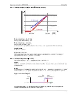
Machine Factor 

The machine factor establishes the relationship between sensor frequency and associated speed. 
 

Machine Factor = Frequency 


                    RPM 

 
See section  
4.2  Machine Factor. 


Once the correct machine factor is entered, all other settings e.g limits are made in RPM.  
 

Minimum Measuring Time 

The minimum measuring time determines the time during which the input frequency is measured. Once 
this time has lapsed, the calculation is made following the end of the running signal period. The 
minimum measuring time may be increased to filter out frequency jitter so as to display a stable reading 
but at the cost of increased reaction time. 
 

Minimum Displayed Value 

The minimum displayed value is a measured value under which “0000” is displayed.


Alarm Definition 

This function defines the alarm. It may be only system error or a logical OR combination of system error 
OR sensor monitoring. During an alarm the LED is off. In addition, the relay is deactivated and the 
analog output goes to 0mA irrespective of the output range. 


8.5.2   Sensor Parameter (Configuration 

Æ

 Sensor) 

Sensor Type 

The type of sensor to be used is defined here. 
<Sensor active> is for monitoring sensors powered by SWTD-1000 including 2 wire sensors supplied via 
the internal pull up resistor. (Jumper J1).  
<Sensor passive> is for monitoring non powered sensors e.g. 2 wire VR (passive) sensors. 
See also section 0 9.4.1   Sensor Fault (Sensor Monitoring). 
 

Sensor Iinput 

The sensor input “analog” (Sign) or “digital” (IQ) is defined here. 
 

Sensor Current Minimum 

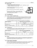
As long as the sensor current consumption lies above the value <Current Minimum>, the sensor is 
considered to be functioning correctly. 
 

Sensor Current Maximum 

As long as the sensor current consumption lies below the value <Current Maximum>, the sensor is 
considered to be functioning correctly. 


Summary of Contents for SWTD-1000

Page 1: ...3690 NW 53 rd Street Fort Lauderdale FL 33309 Ph 954 739 4300 Fax 954 486 4968 www dynalco com SWTD 1000 Speed Switch Transmitter Operating Manual ...

Page 2: ...mmunications 12 8 3 PC Software Settings 12 8 3 1 Interface Settings Æ Interface 12 8 3 2 Display Interval Settings Æ Display Interval 12 8 4 Parameter List and Ranges 13 8 5 Parameters 14 8 5 1 System Parameters Configuration Æ System 14 8 5 2 Sensor Parameter Configuration Æ Sensor 14 8 5 3 Analog Output Configuration Æ Analog Output 15 8 5 4 Limit Configuration Æ Limit 15 8 5 5 Relay parameter ...

Page 3: ...ment or plant Instruments in a doubtful condition after electrical climatic or mechanical overload must be immediately disconnected and returned to the manufacturer for repair 2 Product Features The SWTD 1000 measures and monitor frequencies speed proportional values in the range 0 to 35 000 Hz The following are available 1 Current output 1 Sensor frequency output 1 Relay 2 Limits 2 Parameter sets...

Page 4: ... typically teffective Fixtime max tmax 2 x Fixtime Input frequency period Fixtime Input frequency End of Fixtime Ensuing edge Period of input signal Fixtime time max tmax 2 x input frequency period In the event of sensor signal failure teffective Fixtime 2 x last input frequency period Resolution 0 05 Power supply range 10 36 VDC Power consumption 10 V 2 3 W 24 V 2 6 W 36 V 3 0 W PSU failure bridg...

Page 5: ...ly with Jumper J1 Trigger level adaptive Trigger level Configurable with Jumper J2 250mV 6 5V 500mVpp Factory configuration 28mV 6 5V 20mVrms Screen A terminal is provided for the sensor cable screen This terminal is connected to the sensor supply 0V 0VS Sensor monitoring 1 of 3 settings may be configured via software No Sensor Monitoring Monitoring of powered sensors Also for 2 wire sensors suppl...

Page 6: ...ng Monitoring of powered sensors Also for 2 wire sensors supplied via the Pull up resistor Jumper J1 Æ The sensor is considered to be defective if the sensor current consumption falls outside of Imin and Imax Imin 0 5 25mA Imax 0 5 25mA 3 2 3 Sensor Supply SWTD 1000 14 V short circuit proof 5V short circuit proof SWTD 1000 SWTD 1000 Current mA Voltage V Voltage V 0 14 29 5 50 1 14 23 5 41 5 14 13 ...

Page 7: ...Analog Output SWTD 1000 Type Current 0 20 4 20 mA Load Max 500 Ohm Open circuit voltage Max 12V Operating mode 21 20 12 4 0 speed rpm 0 20mA mode 4 20mA mode initial value final value minimal measured value mA Transfer functions Normal or Inverse rising or falling characteristic speed output normal speed output invers Resolution 12 Bit 4096 steps Max Linear error 0 1 Accuracy 0 5 of the full range...

Page 8: ...ction time Effective measurement time 10 5ms Contact rating AC max 250VAC 1250VA DC Contact isolation 1500 VAC 3 3 3 Open Collector Output Type Opto coupler passive External Pull up R 91 x V Ic nominal 11 mA Load voltage V 5 30 V Max load current 25 mA Isolation 1500 VAC 3 4 Data Communication 3 4 1 Serial Interface RS 232 Physical Layer Similar to EIA RS 232 but with 5V CMOS Level Max cable lengt...

Page 9: ...ld until reset via the binary input The system continuously monitors itself In addition the sensor may be monitored Dependent upon the configuration these conditions can influence the relay and current output The alarm status is indicated via the front panel LED The frequency output open collector output is not influenced by the machine factor and corresponds to the input signal frequency The inpu...

Page 10: ...y Signal Frequency Hz RPM X Teeth or Discontinuities 60 Another way to calculate the machine factor is Machine Factor Teeth or Discontinuities 60 Note The above formulas are based on the gear or target turning at the same speed as the machine being monitored ie no step up or step down gear ratios involved 4 2 1 Displaying Oother Physical Values In principle any physical value that can be measured ...

Page 11: ... of being disconnected via a switch or other emergency means Before switching the equipment on the power supply voltage should be verified to be in the permissible range The sensor cable screen must be connected to the terminal Sh so as to minimize the influence of noise This terminal is directly connected internally to 0VS 6 Connnections 6 1 Front View The SWTD 1000 display along with the RS232 i...

Page 12: ...cable 0VS Sensor Reference voltage VOut Sensor Supply Ana Sensor signal analog Dig Sensor signal digital Open Collector output PO Open Collector Output PO Signal reference for the Open Collector Relay output NC Normally closed NO Normally open Com Common Analog output AO current positive AO current negative Supply 24V Power 10 36 V Gnd Power reference Earth ...

Page 13: ...Jumper position J1 Sensor type J2 Adaptive trigger level range 2 wire sensors with 820Ohm Pull Up resistance 28mV to 6 5V 20mVrms 3 wire and electromagnetic sensors factory setting 250mV to 6 5V 500mVpp factory setting 7 2 Digital Sensor Input IQ No hardware configuration possible or necessary J2 J1 ...

Page 14: ...Bits 8 Stop Bits 2 Connector 3 5mm jack plug 2 3 5 TXD RXD GND TXD RXD GND 5 1 9 6 female The diagram shows the stereo jack plug to D9 connections The tachometer RXD must be connected to the PC s TXD and vice versa The SWTD 1000 does not use a standard RS232 signal 5V 5V but operates at 5V CMOS levels compatible with most PC s as long as the cable is not longer than 2m A suitable cable may be orde...

Page 15: ...rent minimum 0 5 1 5 25 0mA Sensor current maximum 0 5 25 0mA Configuration Analog output Measuring range start value 0 0000 90 of the end value Measuring range end value 1Hz 2000 0 500000 Output range 0 20mA 4 20mA Time constant Damping 0 0 9 9s Configuration Limits Status Limit 1 On Off Status Limit 2 On Off Mode Limit 1 Normal Inverse Mode Limit 2 Normal Inverse Lower Set point Limit 1 0 1 200 ...

Page 16: ... Displayed Value The minimum displayed value is a measured value under which 0000 is displayed Alarm Definition This function defines the alarm It may be only system error or a logical OR combination of system error OR sensor monitoring During an alarm the LED is off In addition the relay is deactivated and the analog output goes to 0mA irrespective of the output range 8 5 2 Sensor Parameter Confi...

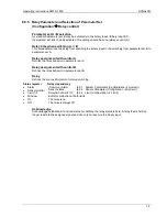
Page 17: ...ing is deactivated when the time constant is 0 0 seconds 8 5 4 Limit Configuration Æ Limit The SWTD 1000 series offers 2 independent limits Æ Limit 1 and 2 Status Limits are selected here If the limit is deactivated the other values such as set points and mode have no further effect Mode In Normal Mode the limit is active as soon as the High set point is exceeded In Inverse Mode the limit is activ...

Page 18: ... A Defines the relay behavior in parameter set A Relay assignment with control B Defines the relay behavior in parameter set B Relay Defines the source information for relay switching Status register Relay dependency Alarm Common Alarm 8 5 1 System Parameters Configuration Æ System Sensormonitor Sensor status 8 5 2 Sensor Parameter Configuration Æ Sensor Limit 1 2 Selection of Limit 1 2 8 5 4 Limi...

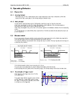
Page 19: ...nning measurement and starts the next The resulting effective measurement time is dependent upon whether the input signal period is longer or shorter than the Fixtime Input signal period Fixtime Input signal period Fixtime Input Frequency End of Fixtime Ensuing edge Fixtime Input period time Effective measurement period tMessung typisch Fixtime tMessung maximal 2 x Fixtime Input Frequency End of F...

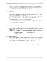
Page 20: ...measured value is between Limts 1 and 2 9 3 2 Parameter set A and B The SWTD 1000 has 2 parameter sets available that define the relay assignment Parameter set A would normally be used If another parameter set is needed e g for test purposes the binary input may be used to change to parameter set B The transfer from parameter set B to parameter set A may be delayed in the range 0 to 2000 seconds T...

Page 21: ...dent on the configuration Outputs in the event of a sensor fault Analog output Alarm Configuration LED Current Relay Only System error On Measured value output per configuration System error OR Sensor monitoring Off 0mA 0V deactivated 9 4 2 System Alarm If the microprocessor detects a checksum fault RAM ROM or EEPROM the measured value is set to 0rpm the analog output goes to 0 4mA and the relay i...

Page 22: ...n Housing Mounting Using DIN 43835 Form B clamps Terminals Detachable Terminal block 2 5 mm 2 Cable or 1 5 mm2 flex AWG 24 AWG 12 UL CSA Sealing to EN 60925 resp IEC 925 Housing IP 40 Terminals IP 20 Dimensions 11 Accessories Interface cable PC SWTD 1000 Part No PC T400 ...

Reviews: