BlueWave® QX4® User Guide
14
To remove the LED Head, slide the retaining body of the Connector away from the
Controller to unlock it from the Jack.
Footswitch Connection
—
Located on the rear panel of the controller. It can be
used as an optional irradiation trigger.
PLC Connection Terminals
—
There are input and output PLC Connection
Terminals that can be used to integrate the unit to an automated assembly line. The
input connections are separated into two main groups: the exposure connections and
the program selection connections. The unit normally has high logic levels (+5 V) and
looks for a low signal (0 V) input. The exposure connections can be used to activate
specific wands or all wands simultaneously. The program selection bits determine which
program mode the unit will operate in. See the
PLC operation Section
for more details.
When the PLC sense connection has a low signal, the Front Screen will display the PLC
connection and will lock out the buttons on the Front Control Display. A low signal on
the interlock connection will lock out the unit.
LED Heads & Lenses
The
BlueWave QX4
led heads are available in three different wavelength: 365 nm
(
RediCure),
385 nm (
PrimeCure)
, and 405 nm (
VisiCure)
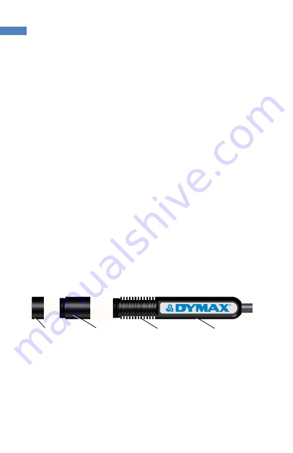
. Each LED head is made up of
three main components: the handle, a collimating lens, and a spot lens. LED head
assemblies are 1.5 M in length. Extensions can be purchased for extra length.
Figure 5. LED Head Components
The handle indicates the wavelength with a type label. The collimating and focusing
lenses in each head are interchangeable, but the handle is unique to a specific
wavelength.
Handle
Collimating Lens
Spot Lens
Cooling Fins


