background image


BlueWave® MX-Series Multichannel Controller User Guide 

appropriate protection/training to avoid injury from the heat. Empirical testing should be used to verify the 
temperature rise in each application. 

Bright Visible Light 

The bright visible energy emitted by curing systems can cause eyestrain if proper eye protection or shielding is not 
used. The use of tinted eye protection and/or opaque/ tinted shielding can be utilized to reduce eyestrain and 
address this concern.  

Dymax tests all LED equipment per IEC62471 and will mark risk group and appropriate warning on each emitter. 

Product Overview 

Description of BlueWave MX-Series Multichannel Controller 

The BlueWave® MX Series multichannel controller, when combined with MX Series emitters, provides 
manufacturers with the curing flexibility they need in a smaller more efficient design.  The unit is comprised of two 
main parts; a multichannel controller with an easy-to-use touchscreen interface and up to 4 high-intensity LED 
emitters.  

With this new controller

, the system can be truly tailored to users’ curing needs –

 allowing them to choose from 

any of the different emitter types and different wavelength LED emitters (365, 385, or 405 nm) in three cure 
pattern formats; Spot, Mini-Flood and Line emission patterns. This flexibility ensures optimal cures are achieved 
across a variety of bond-line geometries and fluid product offerings. Users also have greater set up flexibility; for 
automated curing processes, the emitter can be mounted to robotic arms or further from the controller without 
fear of intensity variations. When used as a bench-top curing system, the unit can be paired with a stand and 
shielding for large area curing.  It can also be used with multiple pathway lightguides for specialized applications 
when paired with MX spot emitters. 

MX Series controllers are available in two different model variants 

 a two channel (MX Series 2CH) that is capable 

of independently controlling up to two emitters, and a four channel (MX Series 4CH) for up to four emitters.  

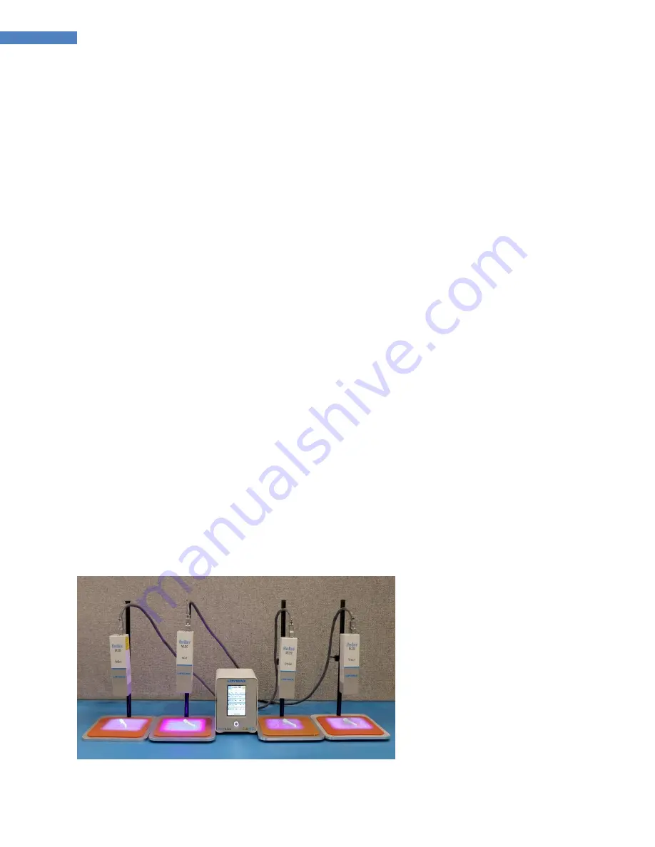
Figure 2. BlueWave® MX-250 System with 4-Channel Controller 


Summary of Contents for BlueWave MX-Series

Page 1: ...ve MX Series Multichannel Controller User Guide 2 4 Channel Controllers for Use with BlueWave MX Series Emitters Instructions for Safe Use Setup and Operation Maintenance Ordering Spare Parts and Accessories ...

Page 2: ...ight curing systems optimize the speed of automated assembly allow for 100 in line inspection and increase throughput System designs enable stand alone configuration or integration into your existing assembly line Please note that most dispensing and curing system applications are unique Dymax does not warrant the fitness of the product for the intended application Any warranty applicable to the p...

Page 3: ...d Inspecting Your Shipment 13 Parts Included 13 System Setup 14 System Connections 14 Modes of Operation 15 Manual Mode 15 Timed Mode 15 PLC Programmable Logic Controller Operation 15 Input Output Interface 16 Examples of PLC Wiring 18 Examples of Master interlock System Health Wiring 20 Operation 21 Admin Screen 21 Touch Screen Interface 21 Irradiation 24 Loading and Saving Programs 25 System Scr...

Page 4: ...31 Product Cleaning 31 System Information 31 Alarms Screen 32 Troubleshooting 33 Spare Parts Accessories 34 Accessories 34 Components Spare Parts 34 Specifications 35 Validation 36 Set Exposure Time Determine Intensity 36 Set Intensity Determine Exposure Time 36 Control 36 Warranty 37 ...

Page 5: ... for additional Dymax locations can be found on the back cover of this user guide Additional resources are available to ensure a trouble free experience with our products Detailed product information on www dymax com Dymax adhesive product data sheets on our website Safety data sheets SDS provided with shipments of Dymax materials Safety WARNING Using this LED controller with the associated light ...

Page 6: ...re designed to maximize operator safety and minimize exposure to light curing energy To use the unit safely it must be set up and operated in accordance with the instructions in this and the respective emitter user guide Please also read and understand the safety considerations unique to LED curing systems as described below WARNING The controller is cooled by natural convection If you block the a...

Page 7: ...g Operators Light curing technology can be a regulatory compliant worker friendly manufacturing process when the proper safety equipment and operator training is utilized There are two ways to protect operators from UV exposure shield the operator and or shield the source Shield the Operator UV Blocking Eye Protection UV blocking eye protection is recommended when operating UV light curing systems...

Page 8: ... interface and up to 4 high intensity LED emitters With this new controller the system can be truly tailored to users curing needs allowing them to choose from any of the different emitter types and different wavelength LED emitters 365 385 or 405 nm in three cure pattern formats Spot Mini Flood and Line emission patterns This flexibility ensures optimal cures are achieved across a variety of bond...

Page 9: ...50 mm 2 in x 2 in curing area for large area coverage The BlueWave MX 275 functions as a line pattern flood curing system with a 5 mm x 50 mm 0 2 in x 2 in asserted curing area To support the use of the multichannel controller emitters must be of firmware revision 1 08 or higher updates can be performed at Dymax Figure 3 Main Components of an MX Curing System 2 4 CHANNEL MX 150 MX 250 MX 275 CONTR...

Page 10: ...ntroller Users can start with 1 Emitter and add others as their applications grow Allows various combinations of different Dymax Emitters MX 150 Emitters compatible with 4 Pole Light Guides 4 MX 150 Emitters each with a 4 Pole lightguide gives you 16 cure spots from a single controller Future compatibility with MX 275 Line Arrays in development 4 MX 275 Emitters produces a high intensity 5mm x 200...

Page 11: ... The front panel Figure 4 features the power button and a touchscreen display through which the unit can be operated Power Button Press the power button to power up the controller Press the button a second time to turn the unit off Figure 4 Front Control Panel Touchscreen Power Button ...

Page 12: ...Channel Controller Rear Panel Figure 6 System Status Located on Rear of Controller PIN 1 Master Interlock input asserted low NOTE MUST BE ASSERTED FOR UNIT OPERATION Factory Jumper Provided PIN 2 ISO Return 1 PIN 3 Reserved PIN 4 Reserved PIN 5 System Health Output Asserted Low No Alarms PIN 6 ISO Return 1 Emitter Interface Connector Power Input Channel I O Interface System Status ...

Page 13: ...and Inspecting Your Shipment Upon arrival inspect all boxes for damage and notify the shipper of box damage immediately Open each box and check for equipment damage If parts are damaged notify the shipper and submit a claim for the damaged parts Contact Dymax customer service for replacement parts The parts below are included in every package order If parts are missing from your order contact your...

Page 14: ...hile power to the unit is on This procedure is usually called hot swapping and should not be performed as it could cause damage to the controller or the LED emitter Always power down the equipment before disconnecting any of these devices 4 The Master Interlock input must be installed using the supplied connector with jumper PIN 1 must be connected to common PIN 2 for normal operation The Master I...

Page 15: ...er counts down to zero the LED is de energized and no curing energy is emitted The timer is reset to the pre set value and the system is immediately ready to run another exposure cycle The LED can be de energized at any time during the curing cycle by simply reasserting the correct trigger input a second time PLC Programmable Logic Controller Operation When in PLC mode an external PLC can control ...

Page 16: ...tputs Connector Pin Signal GND Signal Level Asserted De Asserted I O INPUTS Trigger Minimum pulse width 30 msec Used to start and stop curing cycles IN 1 2 0 VDC Shorted to pin2 24 VDC Open Interlock Input Signal must be asserted for emitter function Momentarily breaking the connection via customer supplied relays or switch contacts will deactivate the emitter FACTORY JUMPERS PROVIDED WITH UNIT IN...

Page 17: ...Alarms PIN 6 ISO Return 1 Table 2 Master System Health inputs and outputs Signal Name Description Isolated Inputs outputs Connector Pin Signal Level Signal GND Asserted De Asserted Master Interlock Input Momentarily breaking the connection via customer supplied relays or switch contacts will deactivate all emitters FACTORY JUMPER PROVIDED IN 1 2 0 VDC Shorted to pin 2 24 VDC Open RESERVED No Conne...

Page 18: ...18 BlueWave MX Series Multichannel Controller User Guide Examples of PLC Wiring Figure 11 PLC Interface Using Dry Contact Switches Figure 12 PLC Interface for intensity Control ...

Page 19: ...al Isolation Figure 14 Emitter Health and UV LED Status Output NOTE The PLC status outputs have a maximum sink current of 5 mA each It is recommended to use a solid state relay with a control current 5 mA where relays are shown in Figure 13 and Figure 16 Recommended Relays Weidmuller 8820710000 Phoenix Contact 2980636 ...

Page 20: ...annel Controller User Guide Examples of Master interlock System Health Wiring Figure 15 Master Interlock Switch Input Figure 16 System Health Output typical relay typical PLC Connection Figure 17 System Health Output to PLC Digital ...

Page 21: ...een allows users to switch back and forth between Administrator Production and PLC modes It is also where the curing parameters are set Figure 18 Admin Screen Touch Screen Interface The touch screen uses two types of inputs via the touch screen Buttons B which executes an action Display Buttons DB which indicates a status or parameter but also functions as a button The following are general descri...

Page 22: ...nd load program s will be disabled The default password is 1234 Settings B Loads the settings screen where the volume language screen brightness and other user settings can be adjusted Triggers DB TR1 TR4 Admin Screen Only Displays the current state of the 4 input triggers Green Active Asserted Yellow Inactive Deasserted NOTE During a cure cycle pressing these will stop any LED emitter operation E...

Page 23: ...wer DB 1 4 The cure power level is displayed as a percentage in the third column under the heading P Pressing this display field will advance the unit to the power level screen Power may be set from 1 100 in 1 increments Note Always use the lowest power setting to achieve cure to extend emitter life Emitter Delay DB 1 4 The cure delay is displayed in the fourth column under the heading D s This is...

Page 24: ...asserted 4 When in manual mode the time indicator will start at zero While the associated trigger input is asserted the time will count up until the associated trigger input is deasserted or it reaches 999 seconds The time value will remain displayed Starting a new exposure will reset the time value to zero immediately and proceed to count up There is a time delay up to 50 milliseconds from assert...

Page 25: ...rams will appear Select the appropriate one and press LOAD The program will load and you will be brought back to the Control Screen System Screens System Information The System Information Screen can be accessed by pressing the Information Button in the top left corner of the Production or Admin Screens Information such as the controller model number and the serial number firmware revision and run...

Page 26: ...s From 0 1 30 seconds the adjustment is made in 0 1 second increments and from 30 999 seconds the adjustment is made in 1 second increments Entering a 0 places this emitter into manual mode You must press the carriage return button to enter a value pressing the back button will abort the command Power Level Screen By pressing the Power Display Button for each channel you can access the power setti...

Page 27: ...hannel you can access the delay setting Figure 24 Delay Display Buttons Figure 25 Cure Delay Settings Screen This screen allows the user to enter the delay time for each emitter The entry range is 0 1 25 seconds From 0 1 10 the adjustment is made in 0 1 second increments and from 10 25 the adjustment is made in 1 second increments This delays the start of the emitter from the time the trigger inpu...

Page 28: ... EXT mode PRG in Program INTENSITY INTENSITY SETTING 1 4 TRIGGER TRIGGER STATUS 1 4 Outputs SYS HLTH SYSTEM HEALTH HEALTH EMITTER HEALTH 1 4 LEDSTATE LED STATUS 1 4 Production Screen The Production screen layout is identical to the administrator screen with the exception it does not have TR trigger buttons All buttons will be disabled except the following Information Production Settings and Alarm ...

Page 29: ...ng any program name and pressing SAVE which advances to the Enter Program Name screen See Below for program name entry Previously saved programs may be recalled by highlighting the desired program name and pressing LOAD Program Name Screen The Program Name field will accept an alpha numeric name of up to 10 characters Figure 28 Program Screen Figure 29 Program Name Screen ...

Page 30: ... where system startup mode Admin Prod PLC can be selected and the Admin password may be accessed Figure 30 Settings Screen User Screen User Modes ADMINISTRATOR controller enters Administrator mode immediately after power up PRODUCTION controller enters production mode immediately after power up PLC controller enters PLC mode immediately after power up PASSWORD Pressing the Password button advances...

Page 31: ...assword Screen Troubleshooting Maintenance Product Cleaning Product cleaning is limited to wiping the product with a damp cloth Do not soak Isopropol Alcohol and mild detergent may be used for cleaning the product System Information The System Information screen provides configuration information for the controller and the emitters attached to it The ALARMS button may be used to access the Alarms ...

Page 32: ...1 4 Light guide must be present MX 150 Only Emitter1 4 LED Over Temperature LED has reached its upper thermal limit Emitter1 4 Error General Errors detected by system Open LED shorted LED over current Emitter1 4 LED Over Current Current monitoring detected LED current above limit Emitter1 4 Fan Speed Low Fan PWM Tach signal is not detected Controller Temperature Failure Controller board temperatur...

Page 33: ...ing not matched to input Trigger setting on Admin screen should match the desired input trigger channel LED head is not connected to the correct port channel Verify that the head is connected to the desired port channel BlueWave MX Controller is operating normally and the head suddenly stops producing light Over temperature shutdown was triggered Verify alarms Interlock is open Verify interlock ju...

Page 34: ...s Item Part Number Emitters BlueWave MX 150 VisiCure 405 nm 42338 BlueWave MX 150 PrimeCure 385 nm 42337 BlueWave MX 150 RediCure 365 nm 42336 BlueWave MX 250 VisiCure 405 nm 42808 BlueWave MX 250 PrimeCure 385 nm 42807 BlueWave MX 250 RediCure 365 nm 42806 BlueWave MX 275 VisiCure 405 nm 43102 BlueWave MX 275 PrimeCure 385 nm 43098 BlueWave MX 275 RediCure 365 nm 43094 Power Cords Power Cord Nort...

Page 35: ...ax timer accuracy 0 1 LED Activation Foot pedal LCD touchscreen or PLC Cooling Convection Air cooled Controller Dimensions W x D x H 3 74 x 6 26 x 5 77 9 5 cm x 15 9 cm x 7 9 cm Weight Controller 2 6 lbs 1 18 kg Unit Warranty 1 year from purchase date Operating Environment 10 to 40 C 50 F to 104 F 0 30 relative humidity non condensing Figure 35 Dimensions Controller ...

Page 36: ...pirical testing determine the exposure time required to achieve a full cure As with any manufacturing process it is advisable to incorporate a safety factor NOTE Dymax recommends intensities low at first to preserve LED life Contact the Dymax Application Engineering Team for additional process support Control Process validation confirms a minimum acceptable intensity Users can then choose to opera...

Page 37: ... use of equipment may void your warranty benefits The use of aftermarket replacement parts not supplied or approved by Dymax Corporation will void any effective warranties and may result in damage to the equipment IMPORTANT NOTE DYMAX CORPORATION RESERVES THE RIGHT TO INVALIDATE ANY WARRANTIES EXPRESSED OR IMPLIED DUE TO ANY REPAIRS PERFORMED OR ATTEMPTED ON DYMAX EQUIPMENT WITHOUT WRITTEN AUTHORI...

Page 38: ...34 Parts Included 13 Product Overview 8 Safety 5 Safety of UV Light Bright Visible Light 8 High Temperature Surfaces 7 UV Exposure 6 Setup 14 Spare Parts 34 Specifications 35 Support 5 System Screens Cure Delay Screen 26 Curing Time Screen 24 Information Screen 24 New Password Screen 30 PLC Screen 27 Power Level Screen 25 Production Screen 27 Program Name Screen 28 Program Screen 28 Settings Scree...

Page 39: ...39 BlueWave MX Series Multichannel Controller User Guide ...

Page 40: ...ing equipment trial rental and leasing programs to assist in such testing and evaluations Data sheets are available for valve controllers or pressure pots upon request MAN090 12 11 2018 Dymax Corporation 1 860 482 1010 info dymax com www dymax com Dymax Oligomers Coatings 1 860 626 7006 info_oc dymax com www dymax oc com Dymax Asia H K Limited 852 2460 7038 dymaxasia dymax com www dymax com cn Dym...

Reviews: