background image


BlueWave® MX-MIM User Guide 

33 

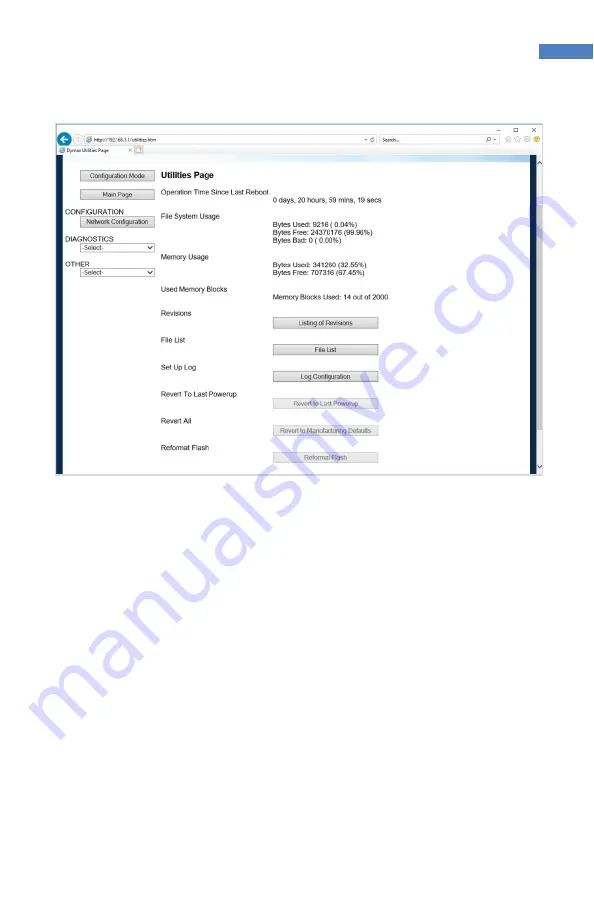
Figure 30. Utilities Page 


Log Configuration 

Enable: 


Enable or disable the logging feature. 

Log Size:


Total number of log messages that will be captured. 

Start Log Size:


Total number of log messages to always display. If set to 
250 and log size is set to 1000, then the first 250 logs will 
always be displayed and the remaining 750 will be the 
most current 750 logs available.  

Task Log Configuration:


Each task listed below represents a different process the 
product has. You have the ability to turn on certain 
capture filters that the diagnostics logging page will 
display. Each bit within the 16-bit value displayed 
represents a different capture filter. 


Bit 0:  Start Up 

Bit 1: Error  

Bit 2: Event 


Bit 3: Assertion 

Bit 4: BSP Comms  Bit 5: Prot Comms 


Bit 6: dbprintf 

Bit 7: Alarm 

Bit 8..15: Reserved 

Summary of Contents for Bluewave MX-MIM

Page 1: ...BlueWave MX MIM User Guide Controller for BlueWave MX Series Systems Instructions for Safe Use Setup and Operation Maintenance Ordering Spare Parts and Accessories ...

Page 2: ...ax does not warrant the fitness of the product for the intended application Any warranty applicable to the product its application and use is strictly limited to that contained in the Dymax Standard Conditions of Sale Dymax recommends that any intended application be evaluated and tested by the user to ensure that desired performance criteria are satisfied Dymax is willing to assist users in their...

Page 3: ...ort 9 Installation 10 DIN Rail Mounting Grounded 10 Factory Reset Button 14 Set Up Web Interface Access 15 Controlling Emitters via the Web Interface 15 EtherNet IP 18 PROFINET 21 Web Guide 23 Log In Page 23 Main Page 23 Network Configuration Page 24 Diagnostics Alarm Log Page 25 Diagnostics Page 27 Emitter Control Page 30 Configuration Mode 31 Troubleshooting 41 Parts and Accessories 44 Specifica...

Page 4: ...me You can also email Dymax at info dymax com Contact information for additional Dymax locations can be found on the back cover of this user guide Additional resources are available to ensure a trouble free experience with our products Detailed product information on dymax com Dymax adhesive product data sheets on our website Safety data sheets SDS provided with shipments of Dymax materials Safety...

Page 5: ...asily configurable with off the shelf applications and can be integrated with a large variety of PLC devices to support any level of system complexity Network Data Formats The controller will automatically detect EtherNet IP or PROFINET connections Unpacking When your BlueWave MX MIM arrives remove all equipment from packaging and verify contents Please retain packing materials in the event the un...

Page 6: ...allation needs review the connections to be made as part of a planned installation utilizing any safety features required Figure 1 BlueWave MX MIM Top View Figure 2 Bottom View Emitter Connectors 1 thru 4 Power Receptacle Ethernet Connector Emitter Interlocks ...

Page 7: ...s of the individual emitter interlocks Upon loss of an interlock connection emitter operation will cease and an alarm will be set This is a safety feature that interrupts power to the emitter and does not rely on firmware controls Upon restoring the interlock connection power will be applied to the emitter and it will be re initialized but will not activate the UV light until commanded to do so by...

Page 8: ...8 BlueWave MX MIM User Guide Figure 4 Controlling 4 Emitter Channels with Master Interlock Alone Figure 5 All Emitter Channels and Master Interlock Defeated with Jumpers ...

Page 9: ...AUTION Power to the controller must be off when connecting or removing the emitter interconnect cables Ethernet Port One 10 100 EtherNet port provides communications across the user s network to the host PLC The use of shielded cables is required to ensure reliable communications Table 1 Table 1 Communication LED Color Description Left LED Speed Indicator Amber or Green Amber ON Operating as a Gig...

Page 10: ...TE 1 inch minimum distance on clearance of vents The DIN rail must also be grounded Figure 6 DIN Rail Mounting Step 1 Figure 7 DIN Rail Mounting Step 2 3 Turn OFF the customer supplied 24V DC supply prior to connecting to unit 4 Wire the 24V DC supply to supplied power plug The chassis must be grounded 5 Insert the power plug PN 43541 into the DC power receptacle Figure 8 6 Install the interlock p...

Page 11: ...shielded Ethernet Cable s to the RJ45 port s Figure 10 Figure 10 Shielded Ethernet Cable in RJ45 Port 9 Connect the selected emitters to the desired channel connectors Figure 11 CAUTION Power to the BlueWave MX MIM controller must be off when connecting or removing the emitter interconnect cables ...

Page 12: ...er cables require a minimum bend radius of four inches to ensure the conductors are not damaged The minimum clearance distance for the interconnect harness is five inches Figure 12 There is 1 inch minimum clearance on vents Figure 13 Figure 12 Interconnect Harness Clearance ...

Page 13: ...iew the system front panel LED indicators Initial state system health red power green After 15 seconds system health green power green NOTE if indicators are not correct please refer to the Troubleshooting Section Minimum 1 inch clearance Minimum 1 inch clearance Minimum 1 inch clearance ...

Page 14: ... accessed using a straightened paper clip or similar device If the reset button is pressed for 5 10 seconds and released the BlueWave MX MIM unit will reset If the reset button is pressed for more than 10 seconds and released the BlueWave MX MIM unit will reset unit and reset to the default IP address 192 168 1 1 Reset Button ...

Page 15: ...y employ other methods they are familiar with to set up an IP address Set up IP address using PRONETA Tech Tip TT075 Set up IP address using IP Setup Tech Tip TT076 Controlling Emitters via the Web Interface 1 Open a web browser and type in the IP address of the desired Dymax device 2 Login as username Admin and password Admin 3 Verify that the Dymax device main web page opens 4 Under DIAGNOSTICS ...

Page 16: ...Figure 17 7 To verify the serial number model type and firmware revision of your emitter s and controller use the drop down arrow These can be compared to the labeling on each individual device 8 Select the next emitter from the drop down and click View 9 Repeat for all emitters Figure 17 Verify Diagnostics ...

Page 17: ...Selecting the appropriate radio button on off press the Update Emitters Button and observe the emitter illumination 12 Verify that the intensity for all connected emitters can be modified via the power level settings Figure 19 Adjust power level press Update Emitters Button and verify with radiometer that power levels increase or decrease as commanded Figure 19 Emitter Controls ...

Page 18: ...t IP Adapter Parameters Table 2 Input Output Assemblies Available Defaults Highlighted Instance Name CIP Data Type Class Instance 0 Revision UINT Max instance UINT 101 0x65 T2O Input Controller 4 Emitters See Table 4 for bytes 0 to 115 USINT 116 113 0x71 O2T Output Controller 4 Emitters See Table 3 for bytes 0 to 7 USINT 8 198 0xC6 Input only heartbeat Heartbeat 199 0xC7 Listen only heartbeat Hear...

Page 19: ...SINT Reset Unit Transition from 0 to 1 will reset the unit 2 SINT Reset Alarms Transition from 0 to 1 will reset alarm state 3 SINT Reserved 4 SINT Set Emitter 1 Power Level Power Level Set Emitter 1 Power Level 1 100 5 SINT Set Emitter 2 Power Level Power Level Set Emitter 2 Power Level 1 100 6 SINT Set Emitter 3 Power Level Power Level Set Emitter 3 Power Level 1 100 7 SINT Set Emitter 4 Power L...

Page 20: ...20 SINT Get Emitter 1 Status Alarm Index See Systems Alarms Section for Specific Alarm Details 21 SINT Get Emitter 1 Status Set Fan Speed 0 100 22 SINT Get Emitter 1 Status LED State 0 LED is OFF 1 LED is ON 23 SINT Get Emitter 1 Status Power Level Emitter Present Power Level Setting 24 27 REAL Get Emitter 1 Status Max Temp Emitter Maximum Temperature Ever Recorded 28 31 REAL Get Emitter 1 Status ...

Page 21: ...erence 0 BYTE Set Emitter LED State Bit 0 Emitter 1 Bit 3 Emitter 4 Turn Emitter LED ON OFF Bit set to 1 ON Bit set to 0 OFF 1 SINT Reset Unit Transition From 0 to 1 Will Reset the Unit 2 SINT Reset Alarms Transition From 0 to 1 Will Reset Alarm State 3 SINT Reserved 4 SINT Set Emitter 1 Power Level Power Level Set Emitter 1 Power Level 1 100 5 SINT Set Emitter 2 Power Level Power Level Set Emitte...

Page 22: ...Emitter 1 Status Alarm Index See Systems Alarms or Table 9 for Specific Alarm Details 21 SINT Get Emitter 1 Status Set Fan Speed 0 100 22 SINT Get Emitter 1 Status LED State 0 LED is OFF 1 LED is ON 23 SINT Get Emitter 1 Status Power Level Emitter Present Power Level Setting 24 27 REAL Get Emitter 1 Status Max Temp Emitter Maximum Temperature Ever Recorded 28 31 REAL Get Emitter 1 Status Temp Emit...

Page 23: ...d description string Network Status Displays status of the connect Ethernet network Dymax Status Display status of communications link to hardware EtherNet IP Status Displays status of communication link to an EtherNet IP Adapter PROFINET IO Status Displays status of communication link to a PROFINET IO Server Figure 21 Dymax Device Main Page 1 These parameters can only be modified in configuration...

Page 24: ...ys the network IP address Subnet1 Displays the network subnet mask Default Gateway1 Displays the network default gateway DNS Gateway1 Displays the network DNS gateway Figure 22 Network Configuration Page It is recommended to leave the DNS gateway set to 0 0 0 0 and the Ethernet Link as auto negotiate If configuring the gateway to use email the DNS gateway must be set 1 These parameters can only be...

Page 25: ...ce Select Device of alarm log to read 0 Controller 1 Emitter1 2 Emitter2 Read Alarms Pressing this button causes the system to read the alarm log of the selected device NOTE 20 most recent alarms will be displayed Figure 23 Alarms Page System Alarms index 1 Emitter1 4 Light guide not installed index 2 Emitter1 4 interconnect cable not logged index 4 Controller Temperature Failure 78 C index 5 Emit...

Page 26: ... 14V index 15 Controller FRAM Failure index 16 Controller FAN Failure index 19 System Overloaded not logged index 100 Emitter1 4 LED Over temperature 80 C index 103 Emitter1 4 LED Over Under current based on power level index 104 Emitter1 4 Fan Failure index 110 Wand1 Temperature Failure 90C index 111 Wand2 Temperature Failure 90C index 112 Wand3 Temperature Failure 90C index 113 Wand4 Temperature...

Page 27: ...Information System Index Select the device info system to be viewed View Retrieve device info for selected system Clear All Values Resets all status parameters to 0 Figure 24 Diagnostics Page EtherNet IP Adapter System Index Select the device info system to be viewed View Retrieve device info for selected system Clear All Values Resets all status parameters to 0 ...

Page 28: ...stics Page Ethernet IP Adapter PROFINET IO Server System Index Select the device info system to be viewed View Retrieve device info for selected system Clear All Values Resets all status parameters to 0 Figure 26 Diagnostics Page PROFINET IO Server ...

Page 29: ...ndex 0 No alarms see manual for alarm details Fan Speed Set fan speed 0 100 LED State 0 OFF 1 ON N A for controller device Power Level Power Level Setting 1 100 N A for controller device Max Temperature Maximum temperature this device has operated under Temperature Present operating temperature for this device Max Current Maximum current draw this device has operated under N A for Controller Devic...

Page 30: ... power level for Emitter1 1 100 Emitter2 On Off Allows the user to turn Emitter2 on or off Emitter2 Power Allows the user to turn adjust the power level for Emitter2 1 100 Emitter3 On Off Allows the user to turn Emitter3 On or Off Emitter3 Power Allows the user to turn adjust the power level for Emitter3 1 100 Emitter4 On Off Allows the user to turn Emitter4 On or Off Emitter4 Power Allows the use...

Page 31: ...l Page NOTE This page is only available when the device is not being controlled by Ethernet protocol commands Configuration Mode Export Import Configuration Save Configuration Save the current system configuration to a file Load Configuration1 Load a saved configuration into the system 1 These parameters can only be modified in configuration mode ...

Page 32: ...splay the catalog number and the revision of software File List Advances to the list of all files stored in the flash file system Log Configuration Advances to the log configuration page page 33 Revert to Last Powerup1 Reverts all settings that have been changed in the current configuration mode to the previously powered up settings Manufacturing Defaults1 Reverts all settings excluding network se...

Page 33: ...ogs will always be displayed and the remaining 750 will be the most current 750 logs available Task Log Configuration Each task listed below represents a different process the product has You have the ability to turn on certain capture filters that the diagnostics logging page will display Each bit within the 16 bit value displayed represents a different capture filter Bit 0 Start Up Bit 1 Error B...

Page 34: ...ptured log data click the Stop Log and Display Button You can change what is displayed by changing the log filters on the bottom of the page The displayed log information is based on the log capture filters configured in Figure 32 of this document Once you stop the log the gateway will not be logging any current messages To resume click the Clear Display Start Log Button ...

Page 35: ...s to diagnostics and configuration on the network The security feature does not protect against Air Gap threats If the gateway can be physically accessed security can be reset All security can be disabled if physical contact can be made From the login page click the reset password button twice You will be forced to do a hard reboot power down on the device within 15 minutes of clicking the button ...

Page 36: ... 32 characters Password Enter a password for the username max of 32 characters case sensitive Re Enter Password Enter the password a second time E mail In case the password was forgotten a user can have their password e mailed to them if e mail was configured Hint A helpful reminder of what the password is Figure 33 Security Configuration Screen Security Configuration Security Levels Each webpage ...

Page 37: ...to login Log In If login is successful the user will be redirected to the main page Send Password to Email Sends the specified user s password to the email configured for that user Display Hint Displays the hint specified for the user if one was set up Reset Password This is used to reset security settings Confirm reset password must be selected to confirm this action Once confirmed there is a 15 ...

Page 38: ...t Once a user is done with a session they may click logout at the top of any page The user may also be logged out for inactivity based off of the log out timer specified during the configuration Figure 36 Log Out Button NOTE Closing the browser is not sufficient to log out ...

Page 39: ...n You can configure up to 10 email addresses SMTP Mail Username The email address that the SMTP server has set up to use SMTP Mail Password If authentication is required enter the SMTP Server s password Optional SMTP Server Enter the name of the SMTP server or the IP address of the server From Email Enter the email that will show up as the sender To Email Enter the email that is to receive the ema...

Page 40: ... made before a restart but they will not be committed until the gateway is restarted When all desired changes have been made press restart now The webpage will redirect to our rebooting page Figure 38 Figure 38 Rebooting Page The reboot can take up to 20 seconds You will know the save was successful if the red box is no longer present If the IP address has not been modified the device will automat...

Page 41: ...y intensity setting through interface Interlock is open Verify interlock jumpers or external controls are in place Verify PLC command structure Interface cable connections loose or damaged Check connections and condition of interface cable Activating wrong channel Verify correct channel is being activated LED head is not connected to the correct port channel Verify that the head is connected to th...

Page 42: ... interconnect cable installation Verify minimum clearance 5 inches is not exceeded Replace emitter interconnect cable 8 Emitter Interlock is open Verify interlock jumper or external control has not been opened defeated Verify PLC command structure 9 15 Internal Failure Return emitter to Dymax 16 Controller Fan Alarm Return controller to Dymax 17 Controller Temperature Warning 69 C Reduce obstructi...

Page 43: ... Alarm Return emitter to Dymax 110 113 QX4 Wand1 Wand 4 Temperature 90 C Reduce intensity setting Improve airflow to BlueWave QX4 wand Reduce ambient temperature 114 117 QX4 Wand1 Wand4 Fault Return wand to Dymax 118 121 QX4 Wand1 Wand4 Lost Comms Verify wand cable installation Replace wand extension cable Check cable connections on both wand and controller ends Inspect wand connector for damage ...

Page 44: ...0 VisiCure 405 nm 42808 BlueWave MX 250 PrimeCure 385 nm 42807 BlueWave MX 250 RediCure 365 nm 42806 BlueWave MX 275 VisiCure 405 nm 43102 BlueWave MX 275 PrimeCure 385 nm 43098 BlueWave MX 275 RediCure 365 nm 43094 Cables Interconnect Cable 2 Meter 42287 Extended Interconnect Cable 10 Meter 43010 Extended Interconnect Cable 20 Meter 43011 Spare Parts Interlock Plug 2 x 5 43536 Power Plug 4 Positi...

Page 45: ...nd PROFINET Please Note Device Level Ring DLR is not supported Physical Dimensions 4 96 H x 7 32 W x 3 50 D Mounting DIN Rail 35 mm top hat style Weight 2 035 lbs Cooling Internal fan no filter Operating Environment Indoors 10 to 40 C 0 80 relative humidity non condensing at sea level Not qualified for outdoor use Storage Conditions 20 to 50 C 0 75 relative humidity non condensing at sea level Sho...

Page 46: ...ent may void your warranty benefits The use of aftermarket replacement parts not supplied or approved by Dymax Corporation will void any effective warranties and may result in damage to the equipment IMPORTANT NOTE DYMAX CORPORATION RESERVES THE RIGHT TO INVALIDATE ANY WARRANTIES EXPRESSED OR IMPLIED DUE TO ANY REPAIRS PERFORMED OR ATTEMPTED ON DYMAX EQUIPMENT WITHOUT WRITTEN AUTHORIZATION FROM DY...

Page 47: ... Configuration 39 Help 4 Installation 10 Network Data Formats 5 Parts List 5 Product Overview 5 Profinet 21 Rebooting Page 40 Safety 4 Security 35 Levels 36 Log In 37 Log Out 38 Set Up 15 Spare Parts 44 Specifications 45 Troubleshooting 41 Unpacking 5 Warranty 46 Web Alarms Page 25 Diagnostic Page 27 Emitter Control Page 30 Log In Page 23 Main Page 23 Network Configuration 24 Utilities Page 32 ...

Page 48: ...their performance testing and evaluation Data sheets are available for valve controllers or pressure pots upon request MAN101 10 30 2019 Dymax Corporation 1 860 482 1010 info dymax com www dymax com Dymax Oligomers Coatings 1 860 626 7006 info_oc dymax com www dymax oc com Dymax Europe GmbH 49 611 962 7900 info_de dymax com www dymax de Dymax Engineering Adhesives Ireland Ltd 353 21 237 3016 info_...

Reviews: