20
W W W . D Y E P A I N T B A L L . C O M
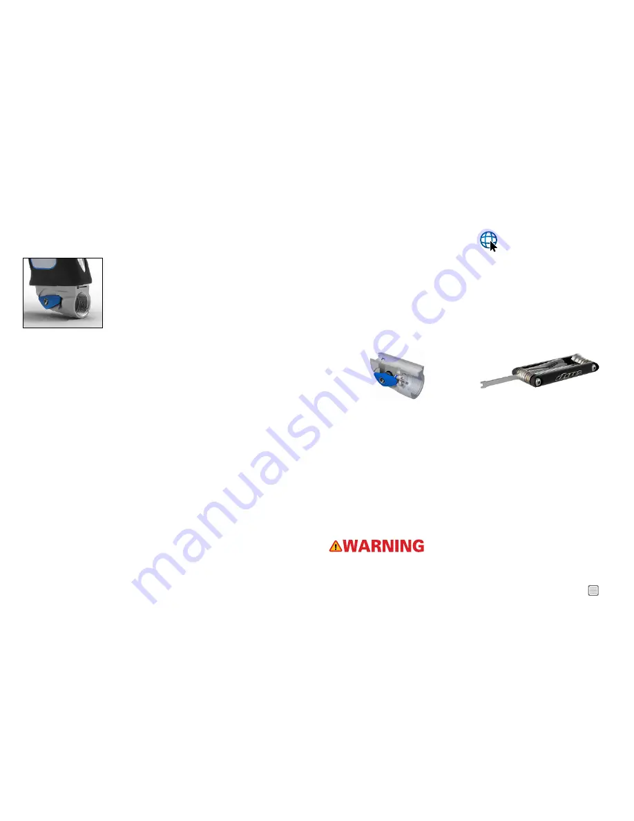
SHIFTPORT ASA
SHIFTPORT ASA
The M3s comes equipped with a the ShiftPort ASA attached to
the bottom of the frame. To turn on the gas supply, rotate the
side lever counter clockwise until the internal stop is reached.
To turn off the gas supply, rotate the side lever clockwise until
the other stop is reached. As you rotate the side lever past the
mid point, the gas stored in the marker will vent.
SHIFTPORT ASA LENGTH ADJUSTMENT
The ShiftPort can be adjusted for optimal comfort. There is a horizontal locking screw
located on the bottom right side of the Ultralite frame. It can be accessed with a 1⁄8” Allen
wrench through a hole in the grip panel. To unlock the ShiftPort ASA for adjustment turn
the locking screw counterclockwise one full turn. Slide the airport back or forth to the
desired location. To lock the airport in place turn the locking screw clockwise until the
airport is firmly secured in place. The ShiftPort ASA has a forward and rearward travel
stop. Do not remove these stops or move the airport past its intended range of travel.
REMOVE PIN-HOUSING ASSEMBLY
To disassemble the ShiftPort ASA use the airport tool included on the DYE Multi-Tool.
However, a pair of needle-nose pliers can be used to unscrew the Pin Housing. Just take
care to not scratch or damage the threads or Pin Housing.
• Insert the airport tool into the Pin Housing and turn counterclockwise 3-4 revolutions.
Note that the airport lever must be in the OFF position for the tool to grab the housing.
Remove housing out of the airport body.
• The pin and
006 O-ring
may or may not come out with the housing, if necessary use
a pair of needle-nosed pliers to pull the pin out and a dental pick to remove the
006 O-ring.
INSTALL PIN HOUSING ASSEMBLY
• Coat the
006 O-ring
in lube and drop it into the airport body. Use the tip of a 1/4”
Allen wrench to fully seat the O-ring in place by pushing gently on it.
• Insert the Pin into the Pin Housing from the backside.
• Place the housing onto the airport tool and insert the housing into the airport body.
• Turn clockwise until the Pin Housing fits snugly into the airport body.
NOTE: IF THE AIRPORT TOOL IS NOT AVAILABLE, A PAIR OF NEEDLE-NOSE
PLIERS CAN BE USED TO UNSCREW THE PIN HOUSING. JUST TAKE CARE TO
NOT SCRATCH OR DAMAGE THE THREADS OR PIN HOUSING.
REMOVE THE AIRPORT LEVER AND INTERNAL CAM
• Remove the DYE sphere jewel located in the middle of the airport lever.
• Use a 3/32” Allen wrench to unscrew the retaining screw and remove the screw
and lever.
• Insert a dental pick into the small slot to pull out the
010 retaining O-ring
. If the Pin
and Pin housing have been removed, the cam should come out with no resistance.
If the Pin and Pin Housing are installed in the airport body, the cam must be in the
ON position so it can be removed.
INSTALL AIRPORT LEVER AND CAM
• Make sure that the Pin is not protruding into the area where the Cam sits.
• Use a dental pick or small Allen wrench to push the pin out of the bore if necessary.
• Drop the Cam into the airport body such that the slot faces upwards and rotate it
clockwise until it drops in place and hits the internal stop.
• Insert the
010 retaining O-ring
into the groove and gently work it in place with a
dental pick or small screwdriver.
• Push the Lever into the Cam slot so that the Lever is facing down, or in the OFF
position.
• Install the retaining screw with a 3/32” Allen wrench and tighten firmly. Turn the Lever
counter-clockwise until it hits the internal stop. Replace the jewel on the Retaining
Screw so that the Dye sphere is correctly oriented.
NOTE: FOR EXPLODED VIEW OF AIRPORT SEE PAGE 27.
EVEN WITH THE AIR SUPPLY REMOVED THE MARKER MAY HAVE GAS INSIDE. BE SURE TO
VENT THIS GAS. MAKE SURE THERE ARE NO PAINTBALLS IN THE BREECH AND DRY FIRE
THE MARKER IN A SAFE DIRECTION.


