23
/
66
SM-1 Ev6/25062014
Picture 40
Picture 41
Picture 42
Tightening moment
Feather
Lock the pulley screw with glue
95Nm
Page 1: ...SM 1 Ev6 25062014 SERVICE MANUAL SPIDER ILD01 G...
Page 2: ...e of the clutch 29 6 10 Exchange of the engine pulley 30 6 11 Adjustment of the tightening belt rollers of the pump and blade drives 31 6 12 Sharpening and exchange of the blade 31 6 13 Exchange of th...
Page 3: ...ettor solenoid 55 7 8 Fuses 56 7 9 Control panel 56 7 10 Accumulator 57 7 11 Steering servomotor APS 57 7 12 Servomotor of the drive control 58 7 13 Control unit NBB 59 Programing of the control unit...
Page 4: ...and brake Hydraulic drive Hydro Gear BDP 21L Hydraulic motor Sauer Danfoss OMP 40 Propelled wheels 4 x 4 Travel wheels palce 16 x 6 5 8 with an arrow V tread pattern Accumulator 12 V 18 Ah gel based F...
Page 5: ...5 66 SM 1 Ev6 25062014 1 Special service tools Chunk for lifted mower 150 x 130 x 80 2 or 4 pieces Straight lath for adjustment of wheel geometry length 1300 mm Engine oil filter loosen jig...
Page 6: ...6 66 SM 1 Ev6 25062014 Hydraulic oil filter loosen spanner Wheel hub puller Geometry adjustment tools No 1 No 2 P N PR001 P N PR002 P N PR006 P N PR004 P N PR001...
Page 7: ...7 66 SM 1 Ev6 25062014 Ampere meter CEM DT 9701 Voltmeter Ben electronic DT 830 D...
Page 8: ...rned fuses Check them Wrong fuel Use BA 95 only The mower does not travel properly at all Not enough oil in the hydraulic circuit refil oil and de aerate properly Driving belts are broken Change them...
Page 9: ...SM 1 Ev6 25062014 3 Basic technical specifications Wheel RPM min Wheel RPM min wheels off the ground blades off SPIDER turtle rabbit engine RPM hydr oil temperature ILD01 25 min 51 min 2750 min 70 C 1...
Page 10: ...0 66 SM 1 Ev6 25062014 4 Regular maintenance SPIDER 4 1 Daily a Check the oil level in engine Picture 1 b Clean the inlet of cooling air for the engine and pump Picture 2 Picture 3 oil dipstick max mi...
Page 11: ...ening and balance Picture 4 d Lubricate the teeth segment guide bushing of the cross Interflon FIN LUBE TF Picture 5 4 2 After first 8 hours a Exchange engine oil see 6 2 Exchange of the engine oil fi...
Page 12: ...air filter Picture 6 Picture 7 4 4 After 50 hours b Lubricate the steering chain spray Interflon FIN LUBE TF Picture 8 c Tighten the steering chain Picture 9 Picture 10 Rough air filter Slack 20 mm C...
Page 13: ...ck the hydraulic oil level HV68 Picture 11 Picture 12 4 5 After 100 hours a Clean the paper air filter Picture 13 b Exchange engine oil c Clean the spark plugs d Clean the cooling engine ribs Oil dips...
Page 14: ...Exchange the paper air filter 2 Picture 9 c Lubricate the wheel arms and wheel bearings Mobilgrease XHP 222 Picture 10 d Check or refill oil inside angular gears MOBILUX EP004 e Lubricate wheel housi...
Page 15: ...c oil 6 3 Exchange the hydraulic oil filter c Change the engine oil 6 2 Exchange of the engine oil filter d Change the fuel filter Picture 18 valve balance arm lifting bar adjustment screw valve clear...
Page 16: ...and add engine oil X Check for loose or lost nuts and screws X Check for fuel and oil leakage X Check or clear air intake screen X Clean air cleaner foam element X Clean air cleaner paper element X C...
Page 17: ...ng and possible injury Turn the wheel transmission housing in the direction to which you will be tilting the mower Always tilt the mower exhaust up in order to prevent the oil from leaking to the air...
Page 18: ...ter put some oil on the filter sealing during assembly Fill up engine oil approximately 1 5 l 1 7 l when exchanging oil filter Picture 23 Picture 24 Check the oil level with the dipstick up to the upp...
Page 19: ...hat they can seal tight Picture 27 Picture 28 Fill up the hydraulic oil HV68 approximately 6 5 l Start the motor a move forward and backward to get rid of air in the hydraulic system the wheels must m...
Page 20: ...r 3 screws of the pump head Picture 31 Tighten the screws back in the pump head Hydraulic tube A short nuts 2 and 3 simultaneously then 4 Picture 32 35 Hydraulic tube B long loosen nut 5 then simultan...
Page 21: ...reverse order Glue the screw on the pump shaft LOCTITE 243 Seal the contact surface of the pump and screw heads with silicone sealing Note After exchanging the pump you need to fill up about 0 5 l of...
Page 22: ...ismount the pulley and hydraulic motor from the cross Picture 36 Picture 36 Picture 37 Mounting Take the above steps in reverse order Seal the hydraulic motor and screws with silicone sealing Glue the...
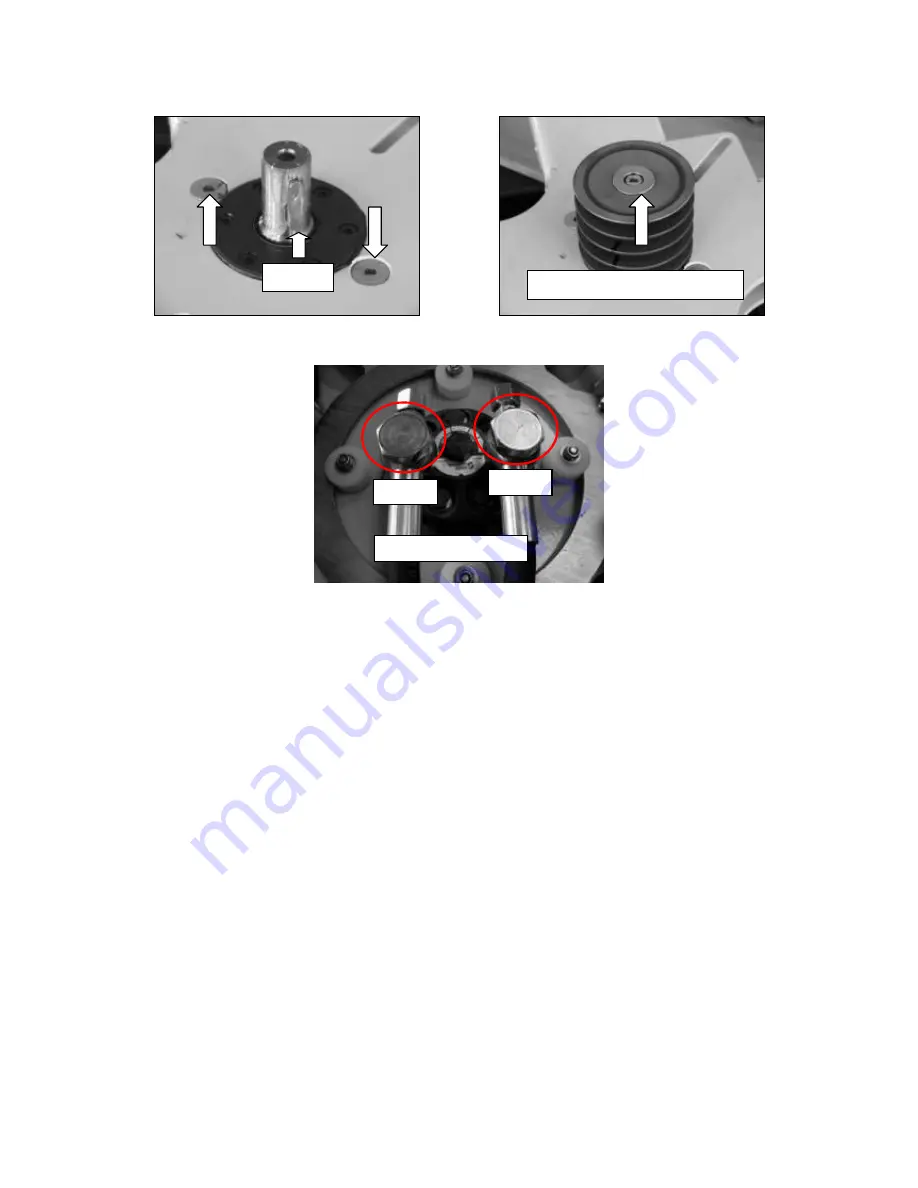
Page 23: ...23 66 SM 1 Ev6 25062014 Picture 40 Picture 41 Picture 42 Tightening moment Feather Lock the pulley screw with glue 95Nm 95Nm...
Page 24: ...belt Lift the mower and tilt it to the side of hydraulic tank Dismount Mowing blade and clutch cover Picture 43 44 Picture 43 Picture 44 Picture 45 Loosen a securing nut of the spring and loosen the b...
Page 25: ...ll V belt Optibelt SUPER TX BX28 x 17 750Lp Picture 46 Turn the clutch to the left to tension all the belts Then tighten securing bolt of the clutch with help of allen key Install tensioning spring ba...
Page 26: ...ue the bearings LOCTITE 638 Press in the blade hub Clean the roller pins lubricate them with grease and glue the thread LOCTITE 243 Check the belt position in middle of the tensioning roller Picture 4...
Page 27: ...holding the clutch Use allen key to turn the clutch to the right Loosen the adjustment nut 1 and securing nut 2 Remove bolt 3 and remove spring 4 with nut 2 Replace the belts SPA1060Lw Picture 52 Pict...
Page 28: ...th sides of the clutch brake disc must move by 0 5 to 1 mm closer further on see 6 9 Exchange of the clutch Start the motor and test the activation of mowing mechanism DON T MOUNT THE BLADE Activated...
Page 29: ...ing Put the clutch cables through the inlet bushing of the case Screw in clutch bolt don t tighten it yet ATTENTION locking pin must match the notch in the skeleton Turn the clutch to the left to tens...
Page 30: ...e mechanism within 0 5s within 5 seconds with the mounted blade When the clutch is activated the brake disc has to move 0 5 to 1 mm closer When the clutch is activated the brake disc must not warm up...
Page 31: ...uring nut holding the spring as far as the spring check the clearance of about 1 mm the belt must be positioned in the middle of tightening roller Picture 60 Picture 60 Picture 61 6 12 Sharpening and...
Page 32: ...32 66 SM 1 Ev6 25062014 Sharpening Along the blade Blade angle about 40 Sharp evenly on both sides of the blade Blade wear allowed Sharp here...
Page 33: ...he left one to the new chain with a connecting link roller chain 084 1 MOFA 1 2 x 3 16 Picture 67 Picture 68 Turn the driving wheels to replace the old chain with a new one this way we cannot impair t...
Page 34: ...supply cables of the electric motor Picture Loosen the driving chain Disconnect the chain and remove it from the motor teeth wheel Loosen the screws of steering motor and exchange the motor Picture 71...
Page 35: ...rection or adjust the steering geometry after mounting MIND a position of the needle bearing securing ring in the arm groove Lubricate the needle bearings pulley shaft and the steering teeth transmiss...
Page 36: ...wing the screws 1 2 and 3 Picture 74 Remove the belts from the pulley Disconnect the following STOP button plug of the electric motor control unit horn choke pull rod hydraulic oil overflow hose pull...
Page 37: ...rod horn control unit plug of the electric motor and STOP button Mount the belts on the pulleys follow the order 1 2 3 4 Picture 80 Push the console on the shaft by hands Tighten the screws follow th...
Page 38: ...the stabilizer journal in hot water for about 5 minutes and press on the ball journal Mount the clamp bushings on the steering shaft and tighten it smoothly see 6 22 Adjustment of the wheel geometry S...
Page 39: ...nger than 30 mm after tightening replace the screw for the original screw Secure it with glue LOCTITE 243 and tighten it ATTENTION Do not knock the wheel transmission clearance Mount the tightening se...
Page 40: ...e bearings need to be exchanged dismount the securing ring of the bearings and press the bearings out Mounting Take the above steps in reverse order Lubricate the shaft with grease Degrease the cone s...
Page 41: ...and secure them with LOCTITE 243 glue and middle one by self securing nut Picture 89 90 Secure the wheel housing spring pin no 2 Picture 89 Mount the big chain wheel and wheel hub see 6 19 Exchange of...
Page 42: ...e geometry adjustment tool no 2 for distance adjustment between the rest of arms Picture 94 Tighten the right side of the stabilizer Check the clearance between the wheels and case Following adjustmen...
Page 43: ...e collision of the screw and driving pulley Picture 99 Put a straight lath along the wheel portals on the left side and to the tyre discs on the right side Adjust the wheels to be parallel Picture 100...
Page 44: ...e it MIND the correct polarity of the electric motor Mounting PAY ATTENTION to the colours of supply cables and their position in the connector Wrong wiring may result in destruction of the electric m...
Page 45: ...ery Tighten the lever nut 30 Nm Adjustment of neutral position Support the mower the wheels must get over the ground Loosen the securing nuts of servomotor pull bars left and right thread Start the mo...
Page 46: ...the ground cable under the relay fixing screw during mounting Check When the relay switches on the voltage must be on both heavy current relay connectors If not check the relay control voltage of the...
Page 47: ...control unit throttle control carburettor solenoid electric motor STOP button horn charger clutch driving servomotor steering motor starter relay and control panel Unscrew the fuse box lid Dismount th...
Page 48: ...ions 1350 rpm Kawasaki maximum revolutions 2800 rpm Correct possition for the spring in the RPM bracket is C and for the servomotor rod is A seasonal maintenance discharge of sludge from the float cha...
Page 49: ...Spring 4 Low Idle Speed Screw 5 Spring 6 Screws 7 Throttle Valve 8 Throttle Shaft 9 Dust Seal 10 Choke Valve 11 Choke Shaft 12 Spring 13 Washer 14 Dust Seal 15 Solenoid Valve 16 Gasket 17 Float Chambe...
Page 50: ...erial 5D 6S 8G 10K 12K Material strength MPa 480 680 580 780 780 980 980 1180 1180 1380 Torque M U max N m M 6 4 3 7 3 9 7 13 5 16 5 M 8 10 17 5 23 33 39 5 M 10 20 5 35 5 47 5 67 80 5 M 8x1 10 17 5 23...
Page 51: ...flon Fin Lube TF Chain spray spray for sliding surfaces water resistant anti adhesive surface Mobilgrease XHP 222 Plastic grease high endurance insoluble lubricant Mobilux EP004 Lubricant for angular...
Page 52: ...El component placement fuses control panel accumulator Linak connector Linak main switch Emergency STOP horn engine rpm servo selenoid starter starter relay connectors clutch charging and ignition Lin...
Page 53: ...er supply ATTENTION dismount only with disconnect accumulator Check If you press main switch contact 1 2 switch off and 3 4 switch on Main switch 7 3 Horn Characteristics supply voltage 12 V red Horn...
Page 54: ...ain both Linak 1 A down 7 A up by Spider loading Check By connectors we connect power supply 12 V We changing power polarity and check if it switching off in end positions For light moving is possible...
Page 55: ...r supply 6 V control f 50 Hz solenoid of the carburator 12V ground black power supply 6V red control yellow Engine rpm servomotor 7 7 Carburettor solenoid electromagnetic valve for fuel closing Charac...
Page 56: ...er electric current value These could cause large damage or even fire to the mower 7 9 Control panel signaling hour meter 1 Power indicator shines green if power is on 2 Signal reception shines green...
Page 57: ...harge for gel accumulator INHACO ACL 1 danger supply long time lower 12 16 V quick accumulator destruction Accu current 7 11 Steering servomotor APS Characteristic 12 V APS 8132186 power supply 12V wh...
Page 58: ...7 12 Servomotor of the drive control Characteristic 12 V PAL both directions max 2 A Motor power supply 12 V controlling power supply 12 V Driving servomotor NBB Current measuring neutral position sen...
Page 59: ...ransmission and reception frequency range 400 477 MHz With loosen and reconnecting cabel harness connector to the control unit be careful to the contacts in the connector Serial number Control unit NB...
Page 60: ...enly during fault free operation Irregular flashing means that the HF channel is probably at fault please set another channel LED 4 red If this led flashes the HF channel is at fault not in the scanne...
Page 61: ...FF or O depends on the cable version Switch on the power on the Spider Operating with Spider Parameter Program Select the tab Com Port settings and select the com port you are using on your computer W...
Page 62: ...To set the tolerance of the set point of the hydraulic servomotor When it is 0 the motor will adjust to the exact angle range for the neutral is 0 so servo will oscillate This can be resolved with inc...
Page 63: ...Load Save parameter to read all data from the NBB receiver and save them in a file You can also load a parameter file and write that to the NBB receiver When you have completed all parameter settings...
Page 64: ...on 12 V and main cable voltage 12 V coil resistant 4 1 ohm Starter relay 7 15 Clutch Characteristic switching voltage 12 V coil resistance 3 4 ohm current switch on 4 2 A Current measuring Clutch con...
Page 65: ...turn off Charging and ignition cables Current measuring 7 17 Measuring list Measuring current voltage and resistance Drains Current Voltage Resistance A V ohm Solenoid carb 0 4 12 40 Clutch switch on...
Page 66: ...66 66 SM 1 Ev6 25062014 7 18 Cable harness circuit NBB Diagram NBB ILD01 G...