background image

10


Istruction Manual ISI SERIES

The regeneration is made up of 7 steps, all associated to the 

letter “C”:

C1  backwash

C2  salt injection and rinse

C3  ri-pressurization

C4  quick rinse

C5  second backwash

C6  second quick rinse

C7  loading of water in the brine

 10.3 QUICK CYCLE:

To check the correct functioning of the different regeneration 

steps, follow the instructions below:

1) Press and hold down 

 until the display shows two lines 

in vertical fall; a manual regeneration cycle will begin.

2) Wait for a few seconds, then press 

. The display will 

show the current step of the cycle, C1.

3) Press 

 at the same time to pass to the following 

step of the regeneration.

4) Wait for a few seconds, then press 

 to see the current 

step of the cycle on the display (“C2”). 

  Repeating the previous commands, it is possible to go past 

all the 7 steps until the “service” position, and then the 

display will show back the set time.

  If you press and hold down 

 at the same time for 

5 seconds, the valve, whatever its position, will go past all 

the steps non-stop, until the service step

 10.4 SELECTING THE REGENERATION PROGRAM

The valve is provided with 4 different regeneration programs: 

U1, U2, U3, U4. Every program has different time values for 

each regeneration step.

The model ISI 5 require the program “U3”

.

The models ISI 8 and ISI 12 require the program “U4”.

To select the regeneration program, press and hold down 

 at the same time for 5 seconds, until the display 

shows the program in use.

Press 

 to select U4 (U3 for ISI 5) and wait for a few se-

conds until the display shows back the set time.

Press and hold down 

 again for 5 seconds and check 

that “U4” appears on the display (U3 for ISI 5).

 11) SETTING AT WORK

After the installation is complete, follow the procedure below:

1.  Close the water inlet and outlet taps (fig. 3, B, D), then 

plug in the fixture.

2.  Press and hold down 

 at the same time for 5 se-

conds; the valve will immediatelly position to the service 

step and the display will show the time.

3. Press   until the display shows two horizontal lines in 

vertical fall.

4.  Wait for a few seconds, then press 

 briefly and check 

that “C1” appears on the display.

5.  Unplug the fixture.

6.  Slowly open the water inlet by half (fig. 3, D) and leave it 

in this position for about 3 minutes.


When all the air is out, open the water inlet completely. 

Let the water flow abundantly until it is crystal clear;

7.  In the meantime, pour some water in the brine tank and 

cover the suction pipe;

8.  Plug in the fixture again.

9. Press 

 at the same time to pass to step C2.

10. Press 

 briefly and check that “C2” is written on the 

display; wait until the water level in the vat decreases and 

almost all the water is sucked in.

11. Press 

 to pass to step C3.

12. Press 

 and check that “C3” appears on the display. 

When the cycle is complete (it will take about 10 minu-

tes), check that the vat still contains some water.

13. Check that the inlet and outlet taps are completely open 

(fig. 3, B, D).

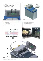
14.  Add salt, up to more than half of the vat (fig. 7).

15. Press 

 briefly, and the display will show a flashing 

dot. It’s now possible to program a regeneration at a fixed 

time.

 12) ADJUSTING THE MIXER SCREW

The water softener supplies water free of hardness. In some 

cases, however, a hardness residual in the water can be im-

portant.

The mixer allows a certain amount of water to pass directly 

from the inlet to the outlet of the water softener, without being 

softened by resins.

Screwing up the mixer screw (fig. 8, E) you can gradually 

increase the hardness of the outcoming water.

Please remember that this operation must be carried out very 

carefully.

At the end of the adjustment, we advise you to let some water 

flow out and to measure its hardness.

 13) MAINTENANCE

 13.1 FOR THE USER

Maintenance for users only consists in refilling the brine pe-

riodically with sodium chloride (NaCl, common salt), in lack 

of which the water softener will not be able to eliminate water 

limy hardness.

ATTENTION! Never use substances different from 

common salt (NaCl).

 13.2 FOR INSTALLERS

For an ideal working, it is advisable to perform the following 

operations periodically:

1) Clean the brine and remove any sediment from the suction 

pipe (fig. 1) every six months;

2. Clean the injector (fig. 8, B) and its filter (fig. 8, A) at least 

once a year, following the instructions reported below:

•  Close the water inlet and outlet taps (fig. 3, B, D)

•  Press and hold down 

 until the display shows two hori-

zontal lines in vertical fall.

•  Wait for a few seconds, then press 

 briefly to visualize 

the cycle step (C1).

•  Unplug the fixture.

•  Unscrew and remove the ejector (fig. 8, B), the filter (fig. 8, 

A) and the brine control (fig. 8, C).

•  Wash the components with water and make sure the hole 

in the ejector isn’t blocked.

•  Carefully place the parts again in their seats.

•  Slowly open the water inlet and outlet taps, and wait for a 

few minutes.

•  Plug the fixture.

•  Press and hold down 

 at the same time for 5 se-

conds. The valve will automatically position to service step.

•  The display will then show back the time (fig. 6, B)

 14) USEFUL INFORMATION

Experience teaches that often malfunctioning of water softe-

ners is caused by an incorrect outlet pipe installation (fig. 4, 

A). For this reason, we advise you to perform a correct instal-

lation (fig. 3, F), using the outlet pipe provided.

Where possible, it is advisable to install a filter before the 

water softener to get rid of substances that could compromise 

the good functioning of the fixture.

ENGLISH

  instruction manual


water softener 

ISI Series

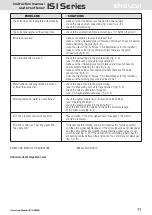
Summary of Contents for ISI 12

Page 1: ...Manuale d istruzioni Instruction Manual Notice d Utilisation Handbuch Manual de Istrucciones Serie ISI ISI 5 ISI 8 ISI 12 ...

Page 2: ...O SPEED CONNECTION INGRESSO ADATTATORE AC ADAPTER INPUT max 1 8 m C max 5 m B A LEGENDA A valvola di non ritorno B rubinetto uscita C rubinetto by pass D rubinetto ingresso E tubo per il troppo pieno F tubo scarico Posizione di lavoro Rubinetto B e D aperti Rubinetto C chiuso Posizione di by pass Rubinetti B e D chiusi Rubinetto C aperto LEGEND A non return valve B outlet tap C by pass tap D inlet...

Page 3: ...GENERAZIONE MANUAL REGENERATION BUTTON B DISPLAY C IMPOSTAZIONE ORA TIME SETTING D DOSAGGIO SALE SALT SETTING E FREQUENZA RIGENERAZIONE REGENERATION FREQUENCY NaCl A FILTRO FILTER B INIETTORE INJECTOR C REGOLATORE SALAMOIA REFILL FLOW CONTROL D ATTACCHI RAPIDI SPEED CONNECTIONS E VITE MISCELAZIONE MIXER SCREW A CAVO ALIMENTAZIONE POWER CABLE B CAVO MOTORE MOTOR CABLE C CAVO LETTORE OTTICO OPTICAL ...

Page 4: ...R LA SICUREZZA Leggere attentamente quanto segue prima di procedere all in stallazione dell apparecchio 1 Prima dell installazione accertarsi che la macchina non presenti anomalie o danni causati dal trasporto in difetto rivolgersi al rivenditore 2 L addolcitore garantisce esclusivamente l addolcimento dell acqua potabile fredda ogni altro uso è da considerarsi irragionevole 3 Le riparazioni e la ...

Page 5: ...ieno poiché l acqua che eventualmente uscirà non sarà in pressio ne fig 3 E e fig 4 B Non collegare il tubo dello scarico di troppo pieno con lo sca rico dell addolcitore per evitare eventuali ritorni d acqua in salamoia 9 PROGRAMMAZIONE DEL TIMER L addolcitore Serie ISI si programma in modo rapido e sem plice grazie a tre pulsanti che permettono di selezionare l ora la quantità di sale e l interv...

Page 6: ...premere brevemente e verificare che sul display appaia C1 5 Scollegare la corrente 6 Aprire il rubinetto d ingresso dell acqua molto lentamente fino a metà fig 3 D e lasciare in questa posizione per circa 3 minuti Quando tutta l aria sarà uscita dallo scarico aprire com pletamente il rubinetto d ingresso e lasciar scorrere ab bondantemente l acqua dallo scarico finché non apparirà limpida 7 Intant...

Page 7: ...a controllare l alimentazione elettrica fig 2 B e fig 9 e la programmazione della valvola vedi 9 programmazione del timer controllare la presenza del sale nella salamoia fig 7 aprire il coperchio frontale della valvola e controllare il corretto avvitamento della vite di miscelazione fig 8 E Err1 Il programma non può più funzionare Premere un tasto se l errore non scompare occorre sostituire il con...

Page 8: ... warnings before installing the fixture 1 Before installation make sure the fixture is not faulty or damaged because of transport failing this please contact your retailer 2 The water softener only guarantees the softening of cold drinkable water Any other use is considered unreasonable 3 Repair and maintenance must be carried out only with the original spare parts 4 Do not expose the fixture to r...

Page 9: ... pipe to the unloading pipe of the water softener in order to prevent any possible return of water in the brine 9 SETTING THE TIMER The ISI Series water softener can be set in a quick and sim ple way thanks to three buttons allowing to select time salt amount and the lapse of time between a regeneration and the next fig 6 During service the display shows the time while during re generation it will...

Page 10: ...ases and almost all the water is sucked in 11 Press to pass to step C3 12 Press and check that C3 appears on the display When the cycle is complete it will take about 10 minu tes check that the vat still contains some water 13 Check that the inlet and outlet taps are completely open fig 3 B D 14 Add salt up to more than half of the vat fig 7 15 Press briefly and the display will show a flashing do...

Page 11: ...the valve is not sucking air where there are the quick connections fig 8 D clean the injector fig 8 B see 13 2 Maintenance for the installer make sure the working pressure is at least 2 bar Water softener salt consumption is higher check the value of salt in the programming or lower than expected see 9 2 Measuring out salt for regeneration fig 6 D check the valve regeneration frequency see 9 3 Reg...

Page 12: ...UCIE SELON SA DURETÉ 7 CONSIGNES DE SÉCURITÉ Nous vous prions de lire attentivement les consignes qui suivent avant de procéder à l installation de l adoucisseur 1 Avant de procéder à l installation contrôlez l appareil pour anomalies ou dégâts de transport éventuels En cas de dég âts adressez vous à votre vendeur 2 Cet adoucisseur ne garantit que pour l adoucissement d eau potable froide toute au...

Page 13: ...r rapport au raccordement de façon à que l eau éventuellement présente sorte en chute et non sous pression fig 3 E et fig 4 B Afin d éviter tous retours d eau dans la saumure ne raccordez pas le tuyau de trop plein avec la vidange de l adoucisseur 9 RÉGLAGE DU TIMER L adoucisseur Série ISI peut être programmé de manière rapide et simple grâce à trois touches qui permettent de sélectionner l heure ...

Page 14: ...aissez le en cette position pour 3 minu tes Lorsqu il n y aura plus d air dans la bouteille ouvrez en tièrement l entrée de l eau Laissez couler l eau abondam ment jusqu à ce qu elle ne devienne claire 7 Au même temps versez manuellement de l eau dans le bac à saumure jusqu à couvrir le tuyau d aspiration 8 Branchez l appareil de nouveau 9 Appuyez sur les touches pour passer à la phase C2 10 Appuy...

Page 15: ...ation fig 6 D contrôlez la fréquence de régénération de la vanne voir 9 3 Fréquence de régénération fig 6 E Après la régénération l eau n est pas adoucie contrôlez l alimentation électrique fig 2 B et fig 9 et le réglage de la vanne voir 9 Réglage du timer contrôlez la présence de sel dans la saumure fig 7 ouvrez le couvercle frontal de la vanne et contrôlez si la vis de mélange et vissée correcte...

Page 16: ...G 3 8 G mit Schnellanschluss Rohr Ø12 mm Abb 2 B 5 MERKMALE DES SPEISEWASSERS Trinkwasser Temperatur min 6 C max 25 C Klarwasser SDI 1 Maximalhärte 90 f 6 MENGE ENTHÄRTETES WASSER JE NACH HÄRTEGRAD 7 SICHERHEITSVORKEHRUNGEN Bitte die folgenden Angaben aufmerksam lesen bevor Sie die Aufstellung des Geräts vornehmen 1 Vor der Aufstellung überprüfen ob die Maschine Unregelmäßigkeiten oder beim Transp...

Page 17: ...triebsstörungen entstehen könnten Durchlöchern Sie die Salzlösung und verschrauben Sie die Überlaufverbindung Dann stecken Sie den Schlauch in den Schlauchanschlussstück ein und schließen Sie den Schlauch an einen Abfluss der tiefer liegt als der Anschluss da das eventuell hinausfließende Wasser nicht unter Druck steht siehe Abb 3 E und Abb 4 B Verbinden Sie den Schlauch für den Überlaufabfluss ni...

Page 18: ...los sen halten Abb 3 B D und der Stecker an den Strom an schließen 2 Drücken Sie gleichzeitig die Tasten für 5 Sekunden Das Ventil wird sich sofort in der Dienstphase positionieren und die Uhrzeit wird auf dem Display erscheinen 3 Drücken Sie die Taste bis zwei waagrechte Linien im senkrechtem Fall auf dem Display erscheinen 4 Warten Sie einige Sekunden und dann drücken Sie kurzeitig die Taste und...

Page 19: ...rontaldecke des Ventils und überprüfen das korrekte Anschrauben der Mischungsschraube Abb 8 E Err1 Das Programm ist nicht mehr betriebsfähig Drücken eine Taste Falls der Fehler nicht vergeht ersetzen die Kontrolle Err3 Die Kontrolle erhält kein Signal von der Ob die Nockenwelle sich dreht warten bis sie sich in der Betriebsposition Nockenwelle findet und der Fehler wird verschwinden Falls der Fehl...

Page 20: ...o que sigue antes de proceder con la insta laciòn del descalcificador 1 Antes de la instalación verifique que la máquina no presen te anomalías o daños causados por el transporte en caso de desperfectos diríjase a su revendedor 2 Este descalcarizador deberà ser destinado solamente al ablandamiento de agua frìa potable cualquier otro uso se considerarà impropio y por tanto irracional 3 Las riparaci...

Page 21: ...cto al enlace ya que el agua que saldrá eventualmente será en caída y no a presión fig 3 E Y 4 B No conectar el tubo del desagüe de demasiado lleno con el desagüe del descalcificador para evitar eventuales retornos de agua en salmuera 9 PROGRAMACIÒN DEL TEMPORIZADOR El descalcificador serie ISI se programa de manera ràpida y simple con tres pulsadores que permiten seleccionar la hora la cantidad d...

Page 22: ...elèctrica 6 Abrir muy lentamente la entrada del agua hasta la mitad fig 3 D y dejar en esta posiciòn para 3 minutos Cuando todo el aire haya salido del desagüe abra completamente la entrada de agua y dejar correr abundantemente el agua hasta que no salga completamente limpia 7 Versar en la cubeta salmuera del agua hasta cubrir el apéndice fig 1 8 Conectar la corriente 9 Pulsar para pasar a la fase...

Page 23: ... 9 2 dosis sal para la regeneraciòn controlar la frecuencia de regeneraciòn de la vàlvula vease 9 3 frecuencia de regeneraciòn fig 6 E Después de la regeneración el agua no está controlar la alimentación eléctrica fig 2 B y 9 y la programación de la ablandada vàlvula vease 9 programaciòn del temporizador controlar la presencia del sal en la salmuera fig 7 abrir la tapa frontal de la vàlvula y cont...

Page 24: ...Timbro del Venditore Installatore Seller Installer s stamp Data Date DATA CONTROLLO ULTIMO CONTROLLO CHECK DATE LAST CHECK ...

Reviews: