DuraMax Woodbridge, Owner'S Manual
The DuraMax Woodbridge shed is a durable and spacious storage solution for your outdoor needs. Make sure to download the Owner's Manual for easy assembly and maintenance instructions. Get your free manual at manualshive.com to ensure you get the most out of your new shed.
Share
Download


Reviews:
No comments
Related manuals for Woodbridge

1000
Brand: HAMPTON BAY Pages: 9
Genesis II
Brand: Campania Pages: 2

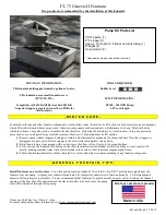
Chatsworth FT-141
Brand: Campania Pages: 2
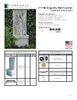
Dragonfly FT-196
Brand: Campania International Pages: 3
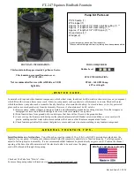
Equinox FT-247
Brand: Campania International Pages: 2
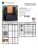
FT-333
Brand: Campania International Pages: 3

grand Hard Disk
Brand: LaCie Pages: 2
00176645
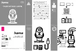
Brand: Hama Pages: 2

9820007
Brand: Hanover Pages: 27

IN30 LED
Brand: iGuzzini Pages: 26

Y-DISK
Brand: PARYA Pages: 6

ARMD BATTING TEE
Brand: Rukket Pages: 2

T0624
Brand: Vaxcel Pages: 7

Roof Zone Penetrator
Brand: Tie Down Engineering Pages: 4

Kota 50l
Brand: NARVI Pages: 7

Deskstar 16GP
Brand: IBM Pages: 2

POLDINA LD0288
Brand: Zafferano Pages: 8

GSS42N
Brand: Napoleon Pages: 24


