11
4.3.4.
Mounting the water cover
1)
Take the water cover with the gasket and the
mounting materials out of the wooden case (see
the lifting instructions of section 3.2).
2)
Inspect the water cover before installation,
especially the coating. Touch up when necessary.
3)
Clean the gasket faces and make sure they are
free of defects (burrs, pits, dents, etc.).
4)
Position the supplied gasket between the water
cover and the tube bundle (item 2 of fig. 7). Make
sure the partitioning corresponds with the
drawing and the water cover.
Make sure the gasket is clean.
Do not use glue, sealant, grease or any other
sealing agent when installing the SBR gasket.
5)
Carefully put the water cover in place. Check the
orientation, refer to the supplied drawing.
Mind the weight. Take care not to damage the
coatings, the gasket or the gasket faces.
6)
Position the supplied bolts and the nuts for the
collar bolts in the bolt holes and fasten hand tight
(see fig. 8a and 8b).
7)
Tighten all bolts and nuts alternate and crosswise
with a torque wrench to guarantee an even
setting of the gaskets.
Refer to section 4.4.4 for tightening torques.
The water cover can be painted on the outside.
Do not paint the inside of the water box.
The paint may
be stripped off by the fluid and blind the tubes.
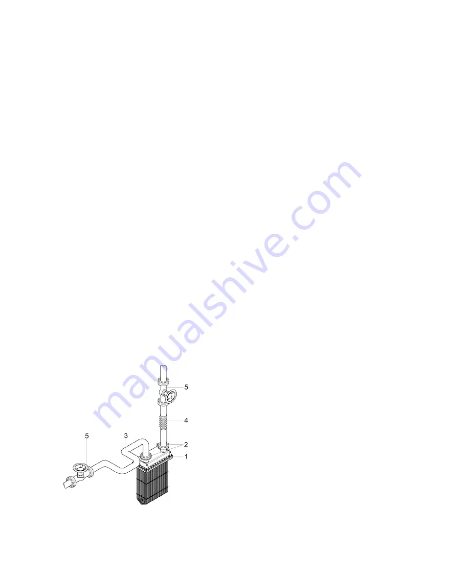
Figure 11. Typical piping installation with an expansion
loop (3), an expansion joint (4) and service valves (5),
connected to the box cooler flanges (1 and 2).
4.4.
FIXING THE PROCESS PIPING
Ensure that all piping will be fixed to the box cooler
without transferring load and (piping) vibrations to
the box cooler.
Install safety devices to prevent overpressure and
overheating (see section 4.4.2).
4.4.1.
Piping design
§
Ensure that the piping is well supported,
independently from the box cooler
and secured as close to the box cooler as possible.
§
Avoid transferring piping vibrations to the heat
exchanger. When needed, fit compensators which
can absorb piping vibrations.
§
Make sure the piping system allow for thermal
expansion and contraction of both the box cooler
and the attached piping. Ensure adequate
flexibility of the piping system (e.g. by fitting
expansion loops and expansion joints, see fig. 11).
Pipe supports should also allow for pipe
movement.
§
Prevent piping misalignment. This will cause
increased nozzle loads. Note that the mentioned
compensators and expansion joints also help to
absorb some piping misalignment.
§
Install adequate means for safe and complete
draining and venting of the box cooler.
Fit air vents at high points to allow for system
bleeding. System bleeding is required to ensure
optimal heat transfer and to prevent fluid
hammer. Venting is also required to enable
complete drainage of the box cooler.
Draining is required to permit safe maintenance
and, when applicable, to prevent freezing during
shutdown periods (see section 5.3).
§
Install manual service valves or bypasses in the
supply and return pipes to enable isolation of the
box cooler from the supply piping. In this way safe
inspection and maintenance can be carried out
without having to shut down or drain a larger
system (see fig. 11).
§
Install -‐ when required -‐ measuring devices to
monitor the pressure, temperature and/or flow
during operation. Fix the devices close to the box
cooler to measure accurately.


