28
6 - COMBUSTION AIR AND VENT PIPING
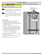
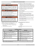
Roof
Terminations
12" (305mm) Min. horizontal separation
between combustion air intake and vent of
same appliance.
12" (305mm) Min. 84" (2.2m) Max. vertical
separation between combustion air intake
and vent of different appliances.
15" (381mm) Max. horizontal length of
vent.
Min. vent/intake between different
appliances 12" (305mm).
Max. allowable total vertical vent length
with outside exposure is 10 ft.(3.05m).
Abandoned unused masonry chimney may
be used as chaseway for combustion air
and vent. Both combustion air and vent
pipe must exit above top of chimney with
clearances as shown in figure 6-11.
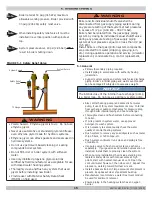
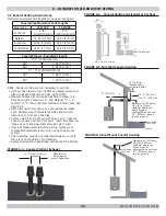
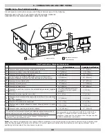
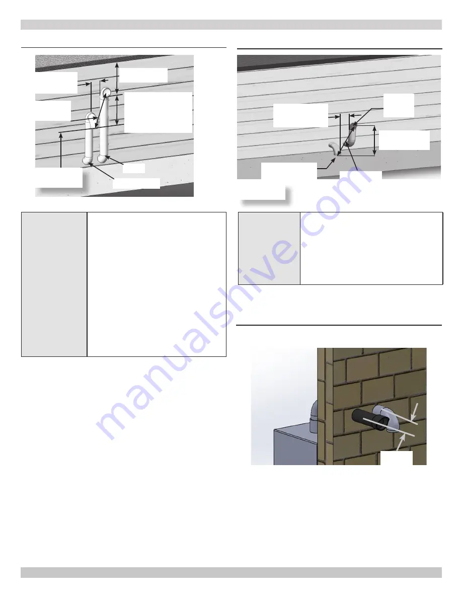
FIGURE 6-14 -Twin Pipe Side Wall Vent
Vent
3" (76mm) Min.
24" (610mm) Max.
Separation
12"(305mm)Min.
From Overhang
12" (305mm) Min.
24" (610mm) Max.
Separation Between
Bottom Of
Combustion Air Intake
And Bottom Of Vent
Combustion Air
Opening
Separation 24"
Min.
Grade, Snow
& Ice
Maintain 12"(305mm) US, 18"(457mm)
Canada clearance above highest anticipated
snow level, 24" (610mm) above roof.
Avoid locations where snow may drift and
block vent and combustion air. Ice or snow
may cause boiler to shut down if vent or
combustion air becomes obstructed.
See Grade,
Snow & Ice
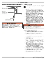
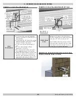
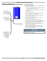
FIGURE 6-15 -Twin Pipe Side Wall with 45° Vent
Vent
45° Elbow
Upward
3" (76mm) Min.
24" (610mm) Max.
Separation
Combustion Air, 90°
Elbow Downward
12" (305mm) Min.
24" (610mm) Max.
Separation
Opening
Separation 24"
Min.
See Grade,
Snow & Ice
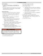
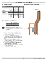
FIGURE 6-16- Single Wall Exhaust Kit and Air Intake
Minimum Distance Center to Center
4
3/4"
[
120
mm]
240011947 REV B, [03/31/2018]
Summary of Contents for DCB-125
Page 2: ...DCC 205 ...
Page 4: ...DCB 165 ...
Page 65: ...61 APPENDIX A WIRING DIAGRAMS A 1 MODELS 125 Heat Only 240011947 REV B 03 31 2018 ...
Page 66: ...62 APPENDIX A WIRING DIAGRAMS A 2 MODELS 165 Heat Only 240011947 REV B 03 31 2018 ...
Page 67: ...63 APPENDIX A WIRING DIAGRAMS A 3 MODELS 150 Combi 240011947 REV B 03 31 2018 ...
Page 68: ...64 APPENDIX A WIRING DIAGRAMS A 4 MODELS 205 Combi 240011947 REV B 03 31 2018 ...
Page 69: ...65 NOTES 240011947 REV B 03 31 2018 ...
Page 70: ...66 NOTES 240011947 REV B 03 31 2018 ...
Page 81: ...9 125 WITH ZONE CIRCULATOR PUMPS 125 with Zone Circulator Pumps PN 240011430 REV G 03 31 18 ...
Page 84: ...12 125 WITH ZONE VALVES PIPING DIAGRAM 125 with Zone Valves PN 240011430 REV G 03 31 18 ...
Page 90: ...18 165 with Zone Valves 165 WITH ZONE VALVES PIPING DIAGRAM PN 240011430 REV G 03 31 18 ...
Page 94: ...22 150 205 WITH ZONE PUMPS WIRING DIAGRAM 150 205 With Zone Pumps PN 240011430 REV G 03 31 18 ...
Page 102: ...30 MODEL 125 Heat Only 125 HEAT ONLY WIRING DIAGRAM PN 240011430 REV G 03 31 18 ...
Page 103: ...31 MODEL 165 Heat Only 165 HEAT ONLY WIRING DIAGRAM PN 240011430 REV G 03 31 18 ...
Page 104: ...32 MODEL 150 Combi 150 COMBI WIRING DIAGRAM PN 240011430 REV G 03 31 18 ...
Page 105: ...33 MODEL 205 Combi 205 COMBI WIRING DIAGRAM PN 240011430 REV G 03 31 18 ...
Page 110: ...38 Low Water Cutoff Detail LOW WATER CUTOFF NO NO YES PN 240011430 REV G 03 31 18 ...
Page 111: ...39 NOTES PN 240011430 REV G 03 31 18 ...
Page 112: ......
Page 115: ......
Page 116: ......

