* *
8 Channel Amplifier Matrix Controller
13
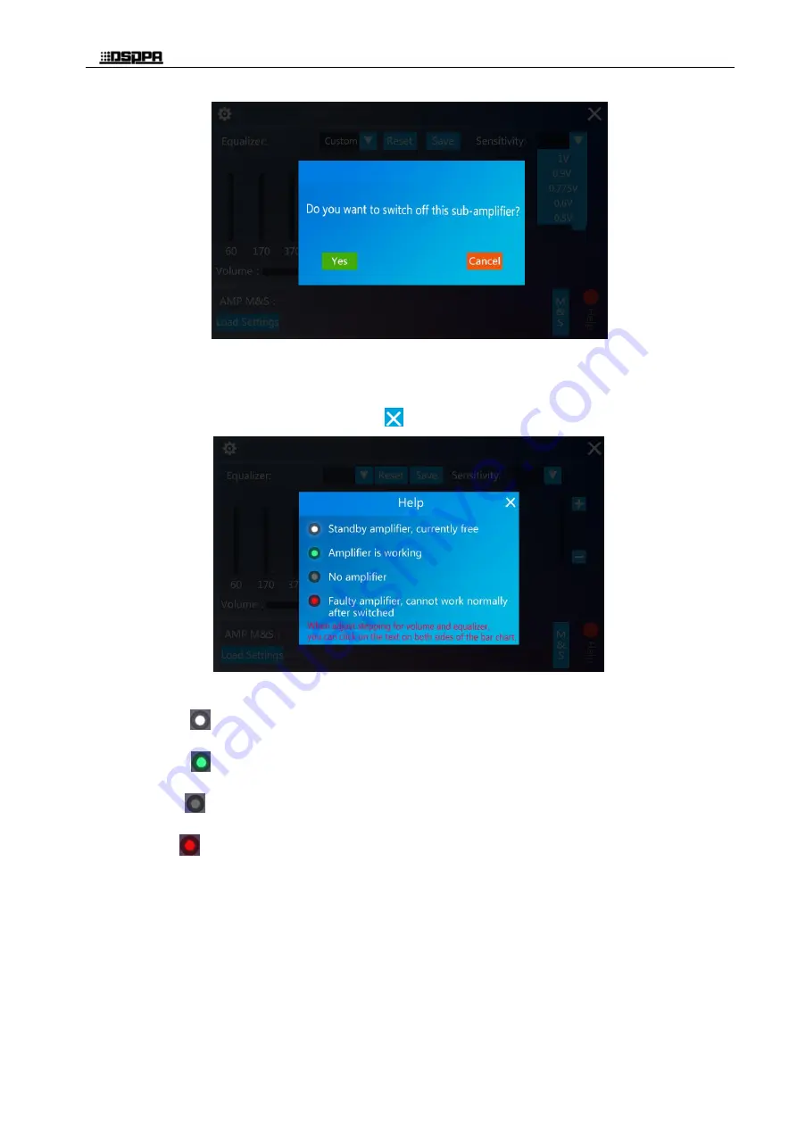
Figure 3-12 Manual call settings interface of main and standby amplifiers
ii.
Click the "help" button in the zone setting interface as shown in Figure 3-10, and the help window
will pop up. The interface will display the color meaning of the standby power amplifier icon as
shown in Figure 3-13. Click the icon
to close the interface.
Figure 3-13 Help interface
Note: White icon
means: the current amplifier is a standby amplifier, and it is free currently;
Green icon
means: the current amplifier is working normally;
Gary icon
means: the current amplifier is now with no amplifier;
Red icon
means: the current amplifier is a faulty amplifier and cannot work normally after switched.
a)
When the device is under 8 mains and 1 standby working mode, there are 9 default external power
amplifiers. As the main interface shown in the Figure 3-14, Channel CH1 -- CH8 are eight working
zones, and the standby power amplifier of each channel is AMP 9 (see Table 3-1 for details). Now the
zone setting interface is as shown in Figure 3-15:


