


G E T T I N G S T A R T E D
5
LCD5500T keypads can each be assigned to a different slot
(1 to 8). Keypad enrollment is required since the panel must
know which slots are occupied in order to generate a fault
when a supervisory is not present.
How to Assign Keypads
Each keypad must be assigned one at a time. After
assigning all keypads, a supervisory reset should
be performed.
To assign a keypad to a slot, enter the following:
1. Enter Installer’s Programming.
2. Press [00] for Keypad Programming.
3. Press [0] for Slot Assignment.
4. Enter a two digit number (11-18) to specify which
supervisory slot the keypad will occupy.
Press the [#] key twice to exit programming. Continue this
procedure at each keypad until they have all been assigned
to the correct slot.
When using more than one LCD keypad, be sure
that only one is assigned to slot number 8.
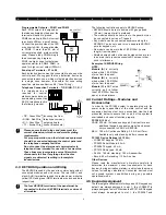
2.6 Supervision
By default, all modules are supervised upon installation.
Supervision is enabled at all times so that the panel can
indicate a trouble if a module is removed from the system.
A connected module which does not show as being present
will appear as a trouble condition and the Trouble light on the
keypad will turn ON. This condition may be due to one or more
of the following reasons:
• the module is not connected to the KEYBUS
• there is a KEYBUS wiring problem
• the module is more than 1,000'/330m from the panel
• the module does not have enough power
For more information regarding module supervision troubles,
please refer to Section 3.4 (“[
✱
] [2] Trouble Conditions”).
Modules will not be automatically supervised if
connected while in installers mode.
2.7 Removing Modules
The panel must be instructed to no longer supervise a module
being removed from the system. To remove the module,
disconnect it from the KEYBUS and reset the supervision
field by entering [92] in the installer’s programming
.
The
panel will be reset to recognize and supervise all existing
modules on the system.
2.8 Zone Wiring
For a complete description of the operation of all zone types,
please refer to Section 5.2 (“Zone Definitions”).
There are several different ways in which zones may be
wired, depending on which programming options have
been selected. Please refer to the following diagrams to
study each type of individually supervised zone wiring.
Any zone defined as Fire will automatically require a
single End of Line (EOL) resistor regardless of which
type of zone wiring supervision is selected
.
(See Section
5.2 “Zone Definitions.”) Reconfiguring the zone supervi-
sion from a non-default setting—from DEOL to EOL or
from NC to DEOL—may disable zones 1-6 while open or
in trouble. To prevent this situation, the system should be
powered down completely and powered up again.
2.8.1 Normally Closed (NC) Loops
2 NORMALLY CLOSED
CONTACTS WITH
NO END OF LINE
RESISTOR
ANY Z
TERMINAL
ANY COM
TERMINAL
NORMALLY CLOSED
CONTACT WITH
NO END OF LINE
RESISTOR
ANY Z
TERMINAL
ANY COM
TERMINAL
This option should only be selected if Normally Closed
(NC) detection devices or contacts are being used
.
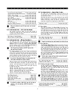
2.8.2 Single End Of Line (EOL) Resistors (5600W)
NORMALLY
CLOSED
CONTACT WITH
END OF LINE
RESISTOR
ANY Z
TERMINAL
ANY COM
TERMINAL
NORMALLY OPEN
CONTACTS WITH
END OF LINE
RESISTOR
ANY Z
TERMINAL
ANY COM
TERMINAL
ANY Z
TERMINAL
ANY COM
TERMINAL
2 NORMALLY OPEN
CONTACTS AND
2 NORMALLY CLOSED
CONTACTS WITH
END OF LINE
RESISTOR
1 NORMALLY OPEN
CONTACT AND
1 NORMALLY CLOSED
CONTACT WITH
END OF LINE
RESISTOR
ANY Z
TERMINAL
ANY COM
TERMINAL
This option should be selected if either Normally
Closed (NC) or Normally Open (NO) detection
devices or contacts are being used.
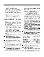
2.8.3 Double End of Line (DEOL) Resistors
Double End of Line resistors allow the panel to determine if
the zone is in alarm, tampered or faulted.
ANY Z
TERMINAL
ANY COM
TERMINAL
ALARM
CONTACT
DOUBLE EOL CIRCUIT
1 NORMALLY CLOSED
CONTACT WITH
5600
END OF LINE
RESISTORS
Ω
This option can only be selected if Normally Closed
(NC) detection devices or contacts are being used
(ie: Do not use DEOL resistors for Fire zones.
Only one NC contact can be connected to each
zone. Multiple detection devices or contacts on a
single loop is not allowed.
The following chart shows zone status under certain
conditions:
• Loop Resistance ................................ Loop Status
• 0
Ω
(shorted wire, loop shorted) ....... Fault
• 5600
Ω
(contact closed) .................... Secure
• Infinite (broken wire, loop open) ....... Tamper
• 11200
Ω
(contact open) ..................... Violated