EN
32
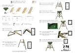
1. Hold the support bar (8) to the spacer piece (9) and place two screws (15) with two
curved washers (12) in the upper two drilled holes.
2. Place the support bar (8) with the spacer piece (9) on the foot with the 3 holes (2)
and place two curved washers (12) and two self-locking nuts (14) on the rear side
of the screws. Make sure that the thread for adjusting the height faces outwards.
CAUTION
:
Do not yet fully tighten the screws!
3. First, attach the cross struts (10) to the two adjacent feet of the support bar (8). To do
this, use one of the short screws (26), the self-locking nuts (14) and two
fl
at washers
(13) on the front and two curved washers (12) on the back. Make sure that the curved
washers (12) are
fi
tted on the back and that the
fl
at washers (13) are
fi
tted on the
front.
CAUTION: Do not yet fully tighten the screws!
4. Then, attach the cross struts (10) to the bottom hole of the support bar (8) with a
long screw (15), a self-locking nut (14) and one
fl
at washer (13) on the front and one
curved washer (12) on the back. Make sure that the curved washer (12) is
fi
tted on
the back and that the
fl
at washer (13) is
fi
tted on the front.
5.
Now fully tighten all screws!
It is essential that you use the tool supplied to tighten
the screws (as described in section “ Assembling the Frame“, point 4). Self-locking
nuts cannot be tightened by hand.
Step 5: Mounting the Handle Bar
1. Undo the thread of the plastic sleeve (7).
2. Push the thread onto the handle pole (5) and insert the handle pole into the plastic
sleeve (7) on the support bar (8).
Summary of Contents for SP150003
Page 2: ......
Page 6: ...DE 6 Geräteübersicht und Lieferumfang ...
Page 23: ...23 EN Device Overview and Parts List ...
Page 39: ...39 FR Vue générale de l appareil et nomenclature ...
Page 56: ...NL 56 Apparaatoverzicht en stuklijst ...
Page 70: ......
Page 71: ......
Page 72: ......