background image

Mounting Applications

Operator’s Manual

14

Pre-Coating Mounting Board cont.

4.  Lay the Leader Board on top of the exposed adhesive on the work table. Push the Leader Board and 

adhesive into the Nip area (where the rollers make contact). When pushing the Leader Board into the 
adhesive, make sure it is parallel to the rollers.

5. Position 

the 

fi

 rst mounting board behind and against the Leader Board. Check for proper alignment and 

feed through the rollers. Feed one board after another, as needed. Position the Leader Board behind the last 
board to be coated so the adhesive can be cut from the roll. Trim the excess adhesive off of the board.

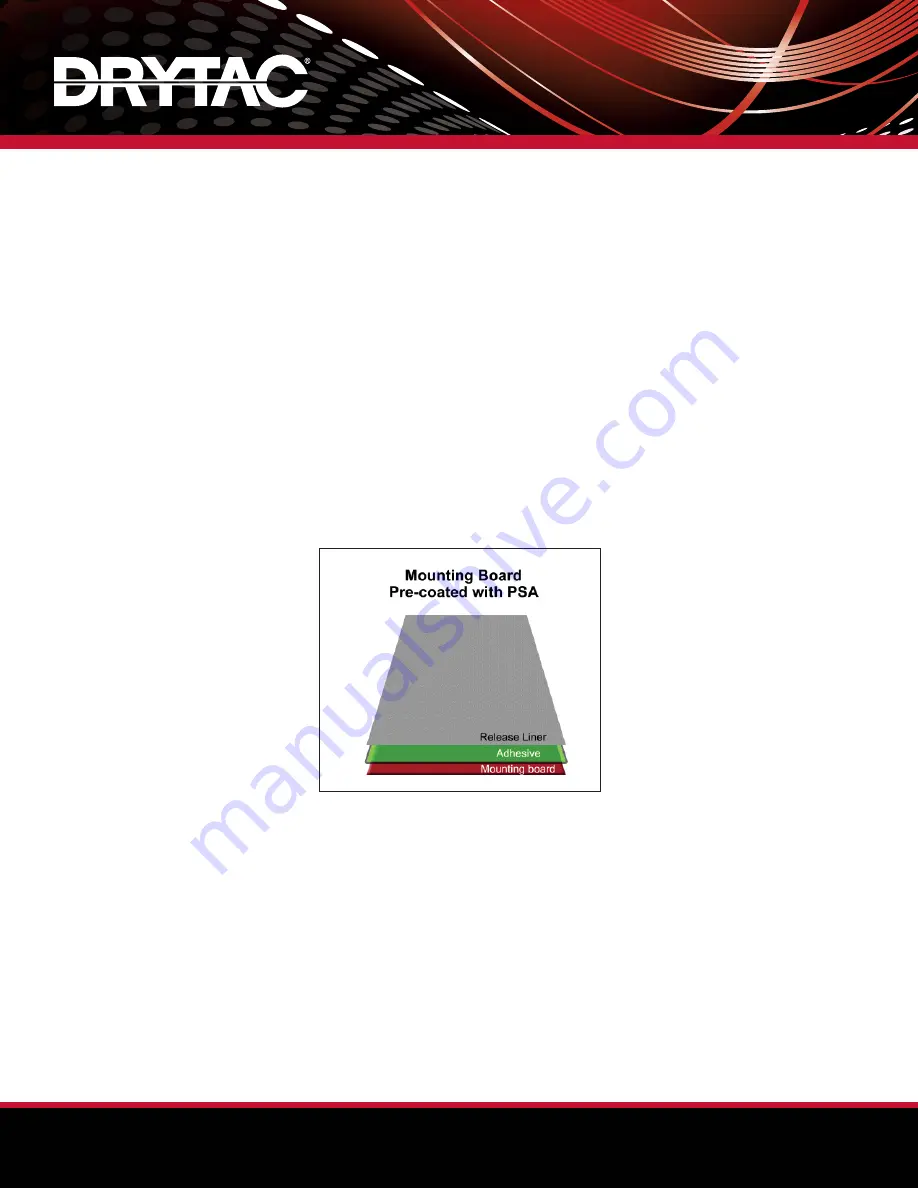
6.  The mounting boards are now pre-coated with PSA, which is still protected by the release liner. The pre-

coated boards can be used for immediate mounting or stored for future use.

TIP

:  

When a graphic image is going to be laminated with a gloss overlaminating 

fi

 lm, the use of very smooth substrates  


with glossy surfaces (such as Masonite

®

) is preferred. This will minimize the effect of board imperfections (i.e.,                     

“orange peel”) in the 

fi

 nished product.

Mounting Graphics to Pre-Coated Boards

1.  Adjust the roller to the height of the substrate.
2.  Expose the adhesive on the board by folding back approximately 1” (25mm) of the release liner.
3.  Using the folded-back release liner as a temporary support bridge, align the graphic image onto the board 

and proceed to “tack” (stick or press down) the leading edge of the graphic onto the exposed adhesive.

4.  Run a Leader Board of the same thickness as the mounting board through the rollers so that the back edge 

of the Leader Board is at the Nip area of the machine. 

Summary of Contents for JetMounter JM55 Force

Page 1: ...at a lower price point Standard features include heavy duty metal construction large diameter non stick silicone rollers variable speed control fold down front table built in flip open storage compartments top and bottom auto grip supply shafts with brake tension control on operator side top auto grip take up shafts with adjustable clutch speed single mechanical height pressure adjustment intercha...

Page 2: ...d Adhesive 13 Pre Coating Mounting Board 13 Mounting Graphics to Pre Coated Boards 14 Laminating Applications 16 Selecting Pressure Sensitive Overlaminating Film 16 Laminating Single Unmounted Image 16 Laminating Single Mounted Image 17 Laminating Multiple Mounted Images 18 Using a Leader Board 19 Carrier Boards and Preparing Mounting Board 19 Care Maintenance 20 Roller Alignment Instructions 21 J...

Page 3: ...ed Range 1 20 fpm 0 5 6 mpm Roll Core Size 3 76mm Packaged for Shipment Width 85 2159mm Depth 34 864mm Height 56 1422mm Weight 875 lbs 397 kg Thank you for purchasing a Drytac JetMounter JM63 Fuzion XD The information contained in this Operator s Manual will explain the basic methods of mounting and laminating with this easy to use roller laminator The Infeed Outfeed Table height of the JM63 Fuzio...

Page 4: ...ikely event that you encounter an issue You will find a section in the Operator s Manual for recording this important information and for noting any future parts or service requests Normal wear and tear damage to the rollers and damage due to abuse improper operation or installation is not covered by this warranty Conditions that will void the warranty include but are not limited to Failure to fol...

Page 5: ... 1 800 280 6013 1 804 222 3094 customerservice drytac com CANADA Drytac Canada Inc 105 Nuggett Court Brampton Ontario L6T 5A9 1 800 353 2883 1 905 660 1748 toronto drytac com JetMounter JM63 Fuzion XD Registration Information COMPANY NAME ADDRESS CITY STATE ZIP SERIAL PURCHASE DATE WARRANTY CARD RETURN DATE BY ...

Page 6: ...d the following safety related information Failure to follow these procedures may result in serious personal injury and or damage to the equipment and materials being used Safety Symbols Danger and or warning symbols indicate imminently and or potentially hazardous situations that if not avoided may result in serious injury or death ...

Page 7: ...rsonal injury or damage to the equipment and materials No persons under the age of 16 should be allowed to operate the equipment DO NOT operate the equipment while under the influence of alcohol prescription drugs or any other substance that could impair your judgment or reaction time Remove any jewelry such as rings bracelets and necklaces prior to operating the equipment Keep loose clothing neck...

Page 8: ...rticularly cautious when operating the equipment with the Foot Pedal as the rollers WILL NOT STOP when the photocells are interrupted An audible alarm will sound but the rollers will continue to turn at a reduced speed Prior to operating the equipment always check that the photocells and buzzer are working properly Use a piece of cardboard to block the photocells to confirm that the alarm sounds a...

Page 9: ...for easy positioning When moving the machine there should be one person on either side to help guide it To eliminate the possibility of it tipping over onto either person push the machine from the ends only Do not push the machine from the front or back Select a clean well lighted work area that allows access to both the front and back of the machine To ensure adequate accessibility and safety pos...

Page 10: ... the Nip area The switch should also be turned to the Off position after processing is completed each day 8 Setup Procedures Operator s Manual Equipment Parts Take ups Unwinds Rollers Idlers Operator Controls A Top Front Take up F Top Heat Assist Roller J Control Panel B Top Rear Unwind Supply G Bottom Cold Roller behind table K Print Guide C Bottom Front Unwind Supply H Top Idler L Infeed Table D...

Page 11: ...ht to show which direction forward or reverse has been selected Ensure the roller has stopped before changing direction To activate the roller in reverse depress the Foot Pedal An audible alarm will sound but the roller will continue to turn at a reduced speed When operating in reverse the machine s photocells will not be active Heat Button A button located on the Control Panel above the Roller Bu...

Page 12: ...t a slow steady speed jog mode until the Foot Pedal is released When the photocell obstruction is clear the set speed will resume by pressing the Roller Button Supply Shaft A shaft used to support and feed a roll of material Rubber cords lock the inside of the core and keep the roll in place Take up Shaft A shaft used to remove and wind up the release liner from the roll of material being used Rub...

Page 13: ...ot in use separate the rollers to prevent flat spots from developing Overlamination and Encapsulation When processing thin graphics the Nip should be closed and the pressure set to 40 Mounting When mounting to substrates the Nip should be set to the thickness of the substrate by turning the Height Wheel The leading edge of the substrate should be inserted and the pressure set according to the dens...

Page 14: ... on both sides of the film to prevent curling Turn the Brakes clockwise to increase tension and counter clockwise to reduce tension Supply Shaft Tension When feeding adhesive or laminate into the rollers it is important to maintain the feed at the same rate that the rollers pull the material through the Nip Slight resistance is usually all that is needed Overtightening the Brakes is rarely the sol...

Page 15: ...economical and allows for maximum flexibility in terms of sizing and substrate selection Pre Coating Mounting Board Pre coating the mounting board means applying a mounting adhesive to one side of the board so that a graphic image can be mounted to the board later The use of a Leader Board is recommended for this process For instructions refer to page 19 1 Adjust the roller to the height of the su...

Page 16: ...the release liner The pre coated boards can be used for immediate mounting or stored for future use TIP When a graphic image is going to be laminated with a gloss overlaminating film the use of very smooth substrates with glossy surfaces such as Masonite is preferred This will minimize the effect of board imperfections i e orange peel in the finished product Mounting Graphics to Pre Coated Boards ...

Page 17: ... cont 5 Square the mounting board with the tacked graphic against the edge of the Leader Board and drape the graphic over the top roller 6 Run the mounting board adhesive graphic image through the rollers while simultaneously pulling the release liner away from and off of the board ...

Page 18: ...structions refer to page 19 Laminating Single Unmounted Image Before processing make sure that the graphic image is clean and free of dust or specks of lint An anti static cloth or anti static wisk is recommended for cleaning the graphic prior to lamination 1 Raise the top roller and insert the Carrier Board Set roller pressure as previously described 2 Pre cut a sheet of overlaminating film from ...

Page 19: ...aphic makes contact with the top roller Complete this step with a consistent motion and do not stop until the entire graphic has passed through the rollers 7 The laminated graphic can now be easily removed from the silicone coated Carrier Board for trimming and mounting Laminating Single Mounted Image Before processing make sure that the graphic image is clean and free of dust or specks of lint An...

Page 20: ... graphic advances to ensure that the liner does not reach the Nip area Use a consistent motion and do not stop until the entire graphic has passed through the rollers The laminated graphic can now be easily removed from the silicone coated Carrier Board for trimming and mounting 9 Trim excess overlaminating film from the edges of the graphic Laminating Multiple Mounted Images 1 For higher volume j...

Page 21: ... to it being mounted to a mounting board substrate To accommodate various artwork formats it is common practice for finishing professionals to stock Carrier Boards in several sizes Making a Carrier Board is similar to pre coating a mounting board When the mounting board is coated with adhesive the silicone coated release liner provides a slick non stick surface on which to laminate graphic images ...

Page 22: ...e up chains located inside the right end case every six months with a premium brand chain lubricant Disconnect power before lubricating the chain Inspection Lubrication Points 1 Use chain lube or WD 40 on drive chains 2 Use oil on brake knob threads 3 Use oil on threads and high quality grease for contact surfaces on lift mechanism components 4 Check oil level on gear box and add appropriate hydra...

Page 23: ... roller until part of it touches the bottom roller If the gap between the top and bottom rollers is uneven an adjustment must be made Proceed to Step 5 If not test for paper travel at 20 and 40 pressure before proceeding A small visual difference in the gap may not necessarily cause poor paper travel or wrinkling and therefore may not require roller adjustment 5 Raise the top roller so that it is ...

Page 24: ...as equal as possible Depending on the paper travel results first loosen the lock nut and then tighten or loosen the adjustment nut Tightening the adjustment nut will increase the pressure Repeat the paper test until travel is less than 0 12 3mm for 20 6m of travel 10 Check the height and pressure sensors to ensure proper operation The height display should read 00 at the Sweet Spot and increase to...

Page 25: ...vailable when the Power Button is pressed b The roller does not rotate unless the Roller Button on the Control Panel is pressed To operate with the Foot Pedal When the Foot Pedal is depressed the bottom roller rotates at the set speed When the Foot Pedal is released the rollers stop rotating unless the operator presses the Roller Button and the machine runs at the set speed When the Foot Pedal is ...

Page 26: ...Operator s Manual 24 JetMounter JM63 Fuzion XD Schematic ...

Reviews: