background image

HeatMax II Furnace Installation and Operation Manual 


62 

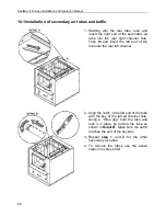
10.1 Installation of secondary air tubes and baffle 


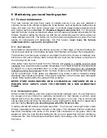
1-  Starting  with  the  rear  tube,  lean  and 

insert the right  end  of the secondary air 
tube  into  the  rear  right  channel  hole.  
Then  lift  and  insert  the  left  end  of  the 
tube into the rear left channel. 


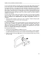
2-  Align the notch in the left end of the tube 

with  the  key of the  left air channel hole.  
Using  a  “Wise  grip”  hold  the  tube  and 
lock  it  in  place  by  turning  the  tube  as 
shown in Detail B.  Make sure the notch 
reaches the end of the key way. 

3-  Repeat  step  1  and  2  for  the  other 

secondary air tubes. 

4-  To  remove  the  tubes  use  the  above 

steps in reverse order. 


Summary of Contents for HEATMAX II DF01001

Page 1: ...nada G3A 2H3 After sale service 418 908 8002 E mail tech sbi international com Please keep this document READ THESE INSTRUCTIONS CAREFULLY BEFORE INSTALLING AND OPERATING YOUR FURNACE This manual is available for free download on the manufacturer s web site It is a copyrighted document Re sale is strictly prohibited The manufacturer may update this manual from time to time and cannot be responsibl...

Page 2: ...about restrictions and installation inspection requirements in your area Please read this entire manual before you install and use your new furnace Failure to follow instructions may result in property damage bodily injury or even death It is important that you follow the installations guidelines exactly You may need to obtain a building permit for the installation of this furnace and the chimney ...

Page 3: ...4 The venting system 13 4 1 The chimney 13 4 1 1 Factory built metal chimneys 13 4 1 2 Masonry chimneys 14 4 1 3 Minimum chimney height 15 4 2 The connector pipe 15 4 2 1 Best practices and requisites of the installation code 15 5 Hot air distribution and air return system 17 5 1 Hot air distribution plenum height according to ceiling height 18 5 1 1 Plenum s minimum height only plenum B must be u...

Page 4: ...1391 39 Appendix 3 Optional Fresh air return adapter AC01392 40 PART 2 OPERATION MAINTENANCE AND TROUBLESHOOTING 41 7 5 How to prepare or buy good firewood 41 7 5 1 What is good firewood 41 7 5 2 Tree species 41 7 5 3 Log length 41 7 5 4 Piece size 42 7 5 5 How to dry firewood 42 7 5 6 Judging firewood moisture content 43 8 Operating your furnace 44 8 1 Your first fires 44 8 2 Lighting fires 44 8 ...

Page 5: ... often should you clean the chimney 59 9 2 3 Cleaning the chimney 60 9 3 Smoke pipe inspection 60 9 4 Blower motor maintenance 60 10 Troubleshooting 61 10 1 Installation of secondary air tubes and baffle 62 11 Exploded diagram and parts list 64 PART 3 FEATURES AND SAFETY 71 12 General information on HeatMax II DF01001 72 12 1 Appliance performance 1 72 12 2 General Features 73 12 2 1 Technical dat...

Page 6: ...in Quebec by APC Association des Professionnels du Chauffage BEFORE STARTING THE INSTALLATION READ ALL THE INSTRUCTIONS BELOW AND MAKE SURE YOU UNDERSTAND THEM IF IN DOUBT CONTACT OUR CUSTOMER SERVICE AT tech sbi international com FAILURE TO COMPLY WITH THESE INSTRUCTIONS MAY RESULT IN HAZARD TO YOUR SAFETY AND WILL AUTOMATICALLY VOID THE WARRANTY Inspect the furnace to make sure that nothing has ...

Page 7: ...FLYERS MAGAZINES AND OR WEB SITES AIR DUCTS SERVING A GARAGE SHOULD NOT BE CONNECTED TO OTHER PARTS OF A HOUSE AND THE DUCTING SERVING A HOUSE SHOULD NOT BE CONNECTED TO A GARAGE MIXING OF CHIMNEY COMPONENTS FROM DIFFERENT SOURCES OR MODIFYING FURNACE COMPONENTS MAY RESULT IN HAZARDOUS CONDTIONS WHERE ANY SUCH CHANGES ARE PLANNED FURNACE BUILDER INTERNATIONAL INC SHOULD BE CONTACTED IN ADVANCE ANY...

Page 8: ...and air return duct system 2 2 Authorized configurations in United States only Parallel installation A represents the wood furnace B represents the gas oil or electric existing furnace Power input B should be equal to or greater than A Each furnace must have its own air return duct system The highest clearances of A and B and hot air distribution and air return ducts of must be respected Static pr...

Page 9: ...inimize the use of 90o elbows and horizontal lengths That ensure a proper installation and safe operation of the appliance Where the owner can ensure cleanliness of the room in the event of negative pressure or temporarily negative Where room to perform maintenance is sufficient and safe 3 2 Certification label N B THIS APPLIANCE MUST BE INSTALLED IN ACCORDANCE WITH THE INSTRUCTIONS ON THE CERTIFI...

Page 10: ... material The clearances shown in this section have been determined by safety tests under normal and even abnormal operating conditions according to procedures set out in standards CSA B366 1 Canada and UL 391 U S A Respecting the minimum clearances is mandatory to prevent risk of fire ...

Page 11: ... C 5 127 mm 5 127 mm D 1 25 mm 1 25 mm E 69 175 cm minimum 69 175 cm minimum F 11 279 mm 11 279 mm G 24 610 mm 24 610 mm Required for maintenance or replacement of components however a 30 762 mm clearance is suggested 3 3 2 Cold air return ductwork Clearances The cold air return system can be connected to a new or to an existing cold air return ductwork In both cases the minimum clearance to combu...

Page 12: ... From door opening C 8 203 mm N A Canada only D 8 203 mm Note 1 N A Canada only E N A USA only Note 2 Steel with a minimum thickness of 0 015 0 38 mm or ceramic tiles sealed together with grout No protection is required if the unit is installed on a non combustible floor ex concrete Note 1 The floor protection at the back of the furnace is limited to the furnace s required clearance A if such clea...

Page 13: ...the proper venting of combustion gases and that such application is verified and authorized by a qualified installer Otherwise the diameter of the flue must be reduced to 6 152 mm by the use of a stainless steel liner made for this purpose 4 1 1 Factory built metal chimneys To be suitable a factory built metal chimney also called high temp chimney must comply with UL 103 HT U S A or ULC S629 Canad...

Page 14: ...ected to a masonry chimney provided the chimney complies with the construction rules found in the building code enforced locally The chimney must have a clay liner If the masonry chimney has a square or rectangular liner that is larger in cross sectional area than a round 6 152 mm flue it should be relined with a suitably listed 6 152 mm stainless steel liner When passing through a combustible wal...

Page 15: ...sed max 6 152 mm to 7 178 mm it must be installed as close as possible the chimney 4 2 1 Best practices and requisites of the installation code o Where passage through a wall or partition of combustible construction is desired the installation shall conform to CAN CSA B365 Installation Code for Solid Fuel Burning Appliances and Equipment o A flue pipe must never pass through a combustible floor or...

Page 16: ...s needs to have either a connector where one end has no fastener or a telescopic length o Removal of the assembly for cleaning should not require that the furnace be moved o The male ends of the sections must be oriented towards the appliance so that falling dust and condensation stay inside the pipe o A straight flue pipe assembly offers the least restriction to gas flow and results in stronger d...

Page 17: ... hot air distribution plenum that may receive 6 to 10 6 152 mm diameter round ducts The installer is responsible of the performance of the distribution ducts and the air return system It will have a direct effect on the ability of the blower to distribute heat efficiently throughout the house The number size and length of the ducts of the distribution system and return air will vary depending on t...

Page 18: ...ents provided with the furnace 10 hot air start off adapter A 4 lids B Type A 10 black screws C 8 selt taping black screws D 5 1 Hot air distribution plenum height according to ceiling height Remember to take into account the 5 127 mm clearance to combustibles above the plenum 5 1 1 Plenum s minimum height only plenum B must be used For a minimum ceiling height of 69 175 cm ...

Page 19: ...possible to cut the plenum extension A of at most 8 203 mm The plenum extension A must therefore have a minimum height of 18 1 2 470 mm Warning The plenum extension A should not obstruct the openings for the hot air distribution of the plenum B The shaded area represents the maximum cutting of plenum extension A 5 1 3 Adjustable height of the plenum A and B without cutting 73 to 88 185 to 224 cm F...

Page 20: ...HeatMax II Furnace Installation and Operation Manual 20 5 2 Assembling the hot air distribution plenum A and B 5 2 1 Assembling the plenum extension A by means of 12 screws and corner reinforcements ...

Page 21: ...Installation and Operation Manual 21 5 2 2 Assembling the plenum B Insert the male end of each panel in the female part of the adjacent panel Secure the assembly by bending the two metal tabs in the center of each corner ...

Page 22: ...HeatMax II Furnace Installation and Operation Manual 22 Install the cover on the part B of the assembly and secure it with 16 screws ...

Page 23: ...d Operation Manual 23 5 2 3 Assembling the plenum extension A to the plenum B Slide plenum B over the plenum extension A to the extent determined in Section 5 1 Using 13 self drilling screws secure the plenum B to the plenum extension A ...

Page 24: ...oles for the installation of the RTD thermal probe Also 5 holes are aligned with the fold of the top of the furnace on the right side and three holes on the other sides This allows you to secure the plenum properly Install the assembly on the furnace taking care to insert the 4 fold on top of the furnace inside the plenum Using 14 screws secure the plenum to the furnace ...

Page 25: ...ibution plenum height according to ceiling height The start off plenum must have a minimum height of 24 610 mm from the top of the furnace X In this case use only the section of the plenum the one with the 10 openings The minimum clearance C between the top of the plenum and the ceiling is 5 127 mm The ducts minimum clearance D to combustible materials is 1 25 mm The ducts may pass through a combu...

Page 26: ...adapter A and slightly fold down one side of the flange to facilitate installation 2 Align the notch previously made on the adapter A with the one of the hot air outlet on the plenum and then turn the adapter until the flange is completely inserted and rotates freely Repeat the above procedure for the other adapters 5 4 3 Minimum amount of outlets and maximum lengths of ducts A minimum of 6 start ...

Page 27: ... maximum run of a main duct is 35 10 7 m It must be reduced from 6 152 mm to 5 127 mm after 20 6 1 m or reduce the main duct by 1 25 mm at every two secondary duct outputs The maximum length of all the main ducts is 180 54 9 m The maximum run of a secondary duct is 10 3 m The maximum length of all the secondary ducts is 100 30 m The finishing grill at the output of a secondary pipe must be made of...

Page 28: ...htly less than the total area of the plenum outlets 160 ACORDING TO THE NATIONAL BUILDING CODE THE BTU H PROVIDED BY AN OUTLET ON THE PLENUM MUST NOT EXCEED 10 250 BTU H 3KW AND THE HOT AIR TEMPERATURE AT THE OUTLET OF A SECONDARY DUCT SHOULD NOT EXCEED 158 F 70 C Once your hot air distribution system is installed make sure to measure the static pressure in the start off plenum Adjust the opening ...

Page 29: ... the outside air intake pipe is 4 102 mm o Mechanical ventilation system if the house is equipped with a ventilation system air exchanger or heat recovery the ventilation system may provide sufficient auxiliary air to the solid fuel unit Otherwise the owner should be informed that the ventilation system may have to be rebalanced by a ventilation technician after the installation of the solid fuel ...

Page 30: ...HeatMax II Furnace Installation and Operation Manual 30 ...

Page 31: ... furnace Install it in the opening provided for this purpose on the start off plenum With the plenum extension A and the plenum B With 6 self taping screws D install the metal plate on the plenum B to block off the 3 holes Make sure the notch towards the bottom Install the RTP probe in the plenum extension A Secure the RTD probe with the two screws provided C Connect the RTD probe on the furnace w...

Page 32: ...sing 6 self drilling screws D install the plate supplied with the furnace on the plenum B Make sure to have the notch on the plate up Install the RTD probe in the hole of the plenum B Secure the RTD probe with two screws C Connect the RTD probe to the furnace with the connector ...

Page 33: ...atic pressure ranges in the warm air plenum of the furnace MODEL DIRECT DRIVE FLOW TEMP VAR BTU H STATIC PRESSURE OPTIONAL FILTER VENT MOT VIT CFM F WOOD INCH OF W C IN HEATMAX II DCT 916 800 5 1 4 4 1800 115 125 000 0 2 20 x 15 x 1 Blower speed Static pressure in WC Pa Flow CFM 1 0 2 50 900 2 0 2 50 1000 3 0 2 50 1200 4 0 2 50 1400 Volts Amps Max Amps Hertz Watts 120 2 8 3 4 60 336 Value as per b...

Page 34: ... C 20 Pa leads to uncontrollable fire even if the air control is in closed position o To prevent excessive draft a barometric control must be installed to control excessive draft It must be adjusted to the maximum draft of 0 06 W C 15 Pa measured at the output of the furnace 7 4 1 The use of a thermometer The first use of a thermometer is to inform the user about the discharge temperature of flue ...

Page 35: ...acturer s instruction always overrides the information published in the following section Thermostat location Must be installed on an inside wall of the house Where it will be the least affected by affected by air currents from a hot air outlet or cold outside walls Must be installed at a minimum of 55 140 cm above the floor Must be installed at a minimum of 15 4 57 m from the furnace and must not...

Page 36: ...e two screws Open the thermostat housing and connect the wires following the manufacturer s instructions Example of thermostat wiring Connect one wire to RH and the other wire to W The red jumper can be left in place For more information refer to the manufacturer s instructions This furnace may be installed in parallel as an add on to an existing furnace in the USA only Such an installation requir...

Page 37: ...inal on the circuit board labeled I interlock of the Add On furnace see Figure 1 2 From the thermostat connected to the existing furnace connect 2 new wire B on the R and W terminals of your thermostat and fix them to the terminal on the circuit board labeled I interlock of the Add On furnace see Figure 1 EXISTING FURNACE ADD ON FURNACE EXISTING FURNACE ADD ON FURNACE ...

Page 38: ...ed the wood furnace will return under the control of its own thermostat Use in thermostat mode To ensure proper operation of the air inlet damper while connected to a thermostat the manual control switch must be maintained in the closed position However when a thermostat is connected to the furnace it is still possible to use the manual control switch to open the air damper if desired Even though ...

Page 39: ...ide of your installation This option includes the filter the filter holder two caps and the screws necessary for the installation Clean and replace filters as often as required Note The operation cost is higher when using a dirty filter 1 filter holder 2 caps 1 filter 15 x 20 x 1 WARNING IT IS NOT RECOMMENDED TO OPERATE THE FURNACE WITHOUT FILTERS THIS APPLIES ESPECIALLY TO TEMPORARY HEATING DURIN...

Page 40: ...ected to the return system and bring it back towards the furnace to be heated This option can be installed on either one of the 3 sides of the blower box Complete installation instruction can be found in the instruction booklet provided when purchasing this option 1 fresh air return adapter 2 caps 1 filter N B TO ENSURE ADEQUATE STATIC PRESSURE THE SYSTEM SHOULD BE BUILT IN A WAY THAT THE VOLUME O...

Page 41: ...od fuel for relatively mild weather in spring and fall because they light quickly and produce less heat Softwoods are not as dense as hardwoods so a given volume of wood contains less energy Using softwoods avoids overheating the house which can be a common problem with wood heating in moderate weather Harder woods are best for colder winter weather when more heat and longer burn cycles are desira...

Page 42: ...m about 3 to 6 76 mm to 152 mm in cross section Having a range of sizes makes starting and rekindling fires much easier Often the firewood purchased from commercial suppliers is not split finely enough for convenient stoking It is sometimes advisable to resplit the wood before stacking to dry 7 5 5 How to dry firewood Firewood that is not dry enough to burn is the cause of most complaints about wo...

Page 43: ... especially if the pieces are big firewood dries more quickly when stacked in the open where it is exposed to sun and wind it takes much longer to dry when stacked in a wood shed firewood that is ready to burn has a moisture content between15 and 20 by weight and will allow your furnace to produce its highest possible efficiency 7 5 6 Judging firewood moisture content You can find out if some fire...

Page 44: ...ire burning quickly A fire that starts fast produces less smoke and deposits less creosote in the chimney Here are three popular and effective ways to start wood fires 8 2 1 Conventional fire starting The conventional way to build a wood fire is to bunch up 5 to 10 sheets of plain newspaper and place them in the firebox Next place 10 or so pieces of fine kindling on the newspaper This kindling sho...

Page 45: ... those log cabin style Light the newspaper 8 2 4 Using fire starters Many people like to use commercial fire starters instead of newspaper Some of these starters are made of sawdust and wax and others are specialized flammable solid chemicals Follow the package directions for use Gel starter may be used but only if there are no hot embers present Use only in a cold firebox to start a fire 8 3 Main...

Page 46: ...the room temperature has fallen Do not operate your furnace at too low a setting Keep the air inlet opened long enough during the fire start up to prevent the fire from smouldering which could stain the glass You will find most of the remaining charcoal at the back of the firebox furthest from the door Rake these coals towards the door before loading There are two reasons for this raking of the co...

Page 47: ...ow each load of wood to burn down so that the space begins to cool off a little before loading 8 3 4 Control of the air supply Once the firewood firebox and chimney are hot you can close the air supply for a steady burn If the flames get very small and almost disappear when you close the air you have closed the air too early or your firewood is wetter than it should be With good fuel and correct a...

Page 48: ... case use soft wood species and place the logs compactly in the firebox so the pieces are packed tightly together You will need to fire the load hot for long enough to fully char the log surfaces before you can turn the air down Make sure the fire is flaming brightly before leaving the fire to burn 8 3 5 3 High output fires for cold weather When the heat demand is high during cold weather you ll n...

Page 49: ...gas decreases which allows better heat transfer in the heat exchanger and chimney The closure of the main air intake reduces the intensity of the flames which indicates the achievement of optimum performance If the flames diminish in intensity at a point where it almost disappears it is an indication that the air inlet damper was closed too soon or the firewood used is dry enough If the wood is dr...

Page 50: ...e or fireplace release odours heat badly cause smoke returns or reversed draft whether there is combustion or not The opening of a window even slightly in calm weather windless eliminates every problem mentioned above The house is equipped with a tight vapour barrier and adjusted windows and or is equipped with an interior air mechanical evacuation device There is excessive condensation on the win...

Page 51: ...rol used 8 6 Ash drawer Your furnace is equipped with an ash drawer to collect ashes produced by the combustion of wood The ash drawer is provided with two 2 wing nuts to hold the door in a close position Operating the furnace with the ash drawer open may seriously damage the furnace The drawer must be emptied regularly 8 7 Prolonged power outage To reduce the risk of overheating during a prolonge...

Page 52: ... covered metal container they should be taken outside immediately The closed container of ashes should be placed on a non combustible floor or on the ground well away from all combustible materials pending final disposal Ashes normally contain some live charcoal that can stay hot for several days If the ashes are disposed of by burial in soil or otherwise locally dispersed they should be retained ...

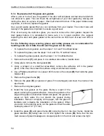
Page 53: ... self adhesive glass gasket and follow the Section 9 1 4 Replacement of the glass and gaskets instructions for installation Check the glass regularly to detect any crack or damage Replace damaged glass immediately do not use the furnace with a broken glass 9 1 3 Door adjustment In order for your furnace to burn at its best efficiency the door must provide a perfect seal with the firebox Therefore ...

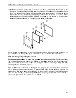
Page 54: ...ined below To replace the glass gasket use the steps 1 to 10 outlined below 1 Remove the door F and place it on a stable work surface handle down 2 Using pliers remove the door gasket A 3 Using a scraper or a small flat screwdriver remove the adhesive left in the gasket grove in the door then clean the surface using a commercial vacuum 4 Use a Phillips screwdriver or a power drill to remove the sc...

Page 55: ...e glass is broken To change the glass perform the same operation described above 9 1 5 Cleaning and painting the furnace Do not attempt to clean or paint the furnace when the unit is hot Painted surfaces can be wiped down with a damp cloth Plated or enameled surfaces may be scratched by abrasive cleaners To maintain the finish at its original brilliance use only a damp soft cloth to clean plated o...

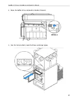
Page 56: ...n the furnace it can mix with creosote and or sooth deposits in the exchangers to form an acid that could accelerate the corrosion process and induce premature decay of the steel Corrosion damages are not covered under warranty Smoke pipe and exchangers must be inspected regularly during the heating season Access to the exchangers is easy and does not require tools 1 Unscrew the wing nut B and rem...

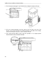
Page 57: ...HeatMax II Furnace Installation and Operation Manual 57 2 Move the baffle of the combustion chamber forward 3 Use the tool provided clean the three exchanger pipes ...

Page 58: ...in the central exchanger 2 will be removed from the front or the rear of the furnace If you remove dirt from the central exchange to the back of the furnace remove the black pipe connector in order to dispose of the dirt 6 Then check that the baffle is clear of ash and reposition it in its original position towards the back of the combustion chamber ...

Page 59: ...ing so the exhaust from the chimney is mostly clear creosote builds up more slowly Your new furnace has the right characteristics to help you to burn clean fires with little or no smoke resulting in less creosote in the chimney 9 2 2 How often should you clean the chimney It is not possible to predict how much or how quickly creosote will form in your chimney It is important therefore to check the...

Page 60: ...d the warranty NOTE Before installing the firebrick check to ensure that none are broken or damaged in any way If so have the damaged ones replaced Check the firebrick for damage at least annually and replace any broken or damaged ones with new ones Inspection and cleaning of the chimney is facilitated by the removable baffle 9 3 Smoke pipe inspection The smoke pipe must be inspected regularly dur...

Page 61: ...d House not insulated enough Ash plug and drawer are not tightly closed Furnace too small for the surface to be heated Unbalanced ventilation system very little heat where the thermostat is located If manually controlled install a wall thermostat Relocate the thermostat Rebalance the ventilation system in order to increase the air flow in the room where the thermostat is located A lot of creosote ...

Page 62: ...ole Then lift and insert the left end of the tube into the rear left channel 2 Align the notch in the left end of the tube with the key of the left air channel hole Using a Wise grip hold the tube and lock it in place by turning the tube as shown in Detail B Make sure the notch reaches the end of the key way 3 Repeat step 1 and 2 for the other secondary air tubes 4 To remove the tubes use the abov...

Page 63: ...ir tubes A can be replaced without removing the baffle board B Important Notes The air tubes are identified for placement as follows Model Type of tube HEATMAX II Front 1 106 holes of 0 109 Middle front 2 53 holes of 0 109 Middle rear 3 53 holes of 0 109 Rear 4 53 holes of 0 109 ...

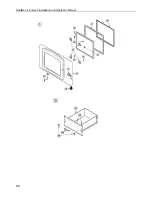
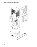
Page 64: ...HeatMax II Furnace Installation and Operation Manual 64 11 Exploded diagram and parts list ...

Page 65: ...HeatMax II Furnace Installation and Operation Manual 65 ...

Page 66: ...HeatMax II Furnace Installation and Operation Manual 66 ...

Page 67: ...HeatMax II Furnace Installation and Operation Manual 67 ...

Page 68: ...HeatMax II Furnace Installation and Operation Manual 68 ...

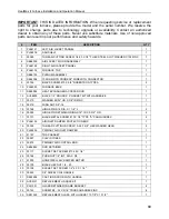
Page 69: ...033 FURNACE BACK 1 11 SE48054 HEAT EXCHANGER ACCESS DOOR 1 12 AC06900 BLACK 1 2 ROUND X 9 GASKET KIT WITH ADHESIVE 1 13 30210 WASHER 29 32 OD X 3 8 ID ZINC 1 14 30416 WING NUT 3 8 16 1 15 30168 HINGE PIN 5 16 DIA X 1 1 4 L 2 16 30055 HINGE PIN RETAINING RING 5 16 ID X 0 512 OD 2 17 30131 BLACK METAL SCREW 10 X 1 2 TYPE A PAN QUADREX 2 18 PL66125 AIR INLET DAMPER PROTECTION BOX 1 19 30026 THREAD CU...

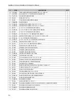
Page 70: ... 3 1 4 X 9 2 52 29010 4 1 2 X 9 X 1 1 4 REFRACTORY BRICK 20 53 24096 ROUND CAST IRON ASH PLUG 1 54 21299 FIREBOX BOTTOM INSULATION 1 55 21084 FIREBOX SIDE INSULATION 2 56 21083 FIREBOX BACK INSULATION 1 57 PL66062 FRONT SECONDARY AIR TUBE 1 58 PL66061 SECONDARY AIR TUBE 3 59 21228 C CAST BAFFLE 18 3 8 X 15 1 2 X 1 1 4 1 60 30494 PANDUIT POLYETHYLENE EXTRUSION 1 61 44091 ROCKER SWITCH 2 POSITION MS...

Page 71: ...FRAME AIR FILTER WITH SUPPORT 20 X 15 X 1 1 81 21044 CARDBOARD FRAME AIR FILTER 20 X 15 X 1 2 82 AC01392 COLD AIR RETURN HOUSING WITH FILTER 1 83 SE45845 HEATMAX II FURNACE INSTRUCTION MANUAL KIT 1 84 AC05959 METALLIC BLACK STOVE PAINT 342 g 12oz AEROSOL 1 85 PL48173 POKER 1 86 PL48170 HEAT EXCHANGER SCRAPER 1 PART 3 FEATURES AND SAFETY Please see Part 1 for installation instructions Please see Pa...

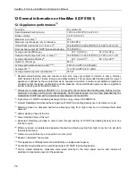
Page 72: ...d the presence of heat distribution systems have a significant impact in making heat circulation optimum 1 Values are as measured per CSA B415 1 10 except for the recommended heating area firebox volume maximum burn time and maximum input capacity Performances based on a fuel load prescribed by the standard at 10 lb ft and with a moisture content between 18 and 28 2 Input value at 10lb ft fuel loa...

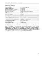
Page 73: ...EPA CSA B415 1 10 USA standard safety UL 391 Canadian standard safety CAN CSA B366 1 East west through the door you see the longitudinal sides of the logs north south through the door you see the tips of the logs Mobile home Canada or manufactured home USA The US department of Housing and Urban Development describes manufactured homes better known as mobile homes as followed buildings built on fix...

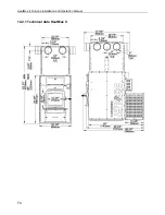
Page 74: ...HeatMax II Furnace Installation and Operation Manual 74 12 2 1 Technical data HeatMax II ...

Page 75: ...HeatMax II Furnace Installation and Operation Manual 75 ...

Page 76: ... 12 4 1 What is your new furnace made of The body of your furnace which is most of its weight is carbon steel Should it ever become necessary many years in the future almost the entire furnace can be recycled into new products thus eliminating the need to mine new materials The paint coat on your furnace is very thin Its VOC content Volatile Organic Components is very low VOCs can be responsible f...

Page 77: ... FROM THE FURNACE WHILE IT IS IN USE DO NOT STORE FUEL WITHIN HEATER MINIMUM INSTALLATION CLEARANCES BURN ONLY SEASONED NATURAL FIREWOOD DO NOT BURN o GARBAGE OF ANY KIND o COAL OR CHARCOAL o TREATED PAINTED OR COATED WOOD o PLYWOOD OR PARTICLE BOARD o FINE PAPER COLORED PAPER OR CARDBOARD o ALL MANUFACTURED LOGS o SALT WATER DRIFTWOOD OR o RAILROAD TIES DO NOT USE LIQUIDS SUCH AS KEROSCENE OR DIE...

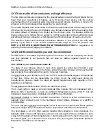
Page 78: ...or more information go to www P65warnings ca gov 13 2Smoke detector We highly recommend the use of a smoke detector It must be installed at least 15 feet 4 57 m from the appliance in order to prevent undue triggering of the detector when reloading 13 3Chimney fire A Chimney fire will happen when the flame from an uncontrollable fire ignites the sooth and creosote deposits in a neglected venting sy...

Page 79: ...ion of the defect The manufacturer may at its discretion fully discharge all obligations with respect to this warranty by refunding the wholesale price of any warranted but defective parts The manufacturer shall in no event be responsible for any uncommon indirect consequential damages of any nature which are in excess of the original purchase price of the product A one time replacement limit appl...

Reviews: