background image


This document and the information contained herein, is the exclusive property of Drivecon and represents a non-public, confidential and proprietary trade secret that 

may not be reproduced, disclosed to third parties, altered or otherwise employed in any manner whatsoever without the express written consent of Drivecon.  

Copyright © (2013) Drivecon. All rights reserved.


CURRENT CONSUMPTION  


Input power 

Min.* 

Max.* 

12V AC 

0.02A

0.6A 

24V AC 

0.02A

0.3A 

48V AC 

0.008A 

0.2A 

115V AC 

0.004A

0.07A 

230V AC 

0.003A 

0.04A 

12V DC 

0.03A

0.5A 

24V DC 

0.02A 

0.3A 


*Minimum current consumption= Receiver powered, no radio session established, nothing else 
activated on the receiver. 
**Maximum current consumption= All relays activated on the receiver. 


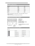
TERMINAL BLOCK FOR INPUT POWER  


TERMINAL BLOCK FOR DIGITAL INPUTS  


Base board: 


33. GND 

38.Digital input 5 

34. Digital input 1 

39.Digital input 6 

35. Digital input 2 

40.Digital input 7 

36. Digital input 3 

41.Digital input 8 

37. Digital input 4 

42. GND 

8

Summary of Contents for PWR LYNK Series

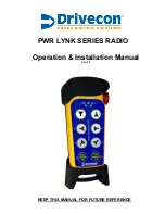
Page 1: ...PWR LYNK SERIES RADIO Operation Installation Manual Ver 1 0 KEEP THIS MANUAL FOR FUTURE REFERENCE ...

Page 2: ......

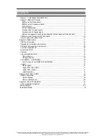
Page 3: ...r Digital inputs 8 LEDs on the expansion board representing the function relays on the base board 9 PWRLynk XIV Transmitter Technical data 10 How to remove the rubber cover 11 Chapter 3 USER GUIDE 12 Start the transmitter 12 Register the transmitter in the receiver 12 Erase the transmitter from the receiver 12 Turn the transmitter off 12 Enter menu mode 13 Replace 14 Frequencies channels 15 Show c...

Page 4: ...te control unit on the machine are not intended to be passed on to the end user Only such information may be passed on to the end user that is needed to operate the machine correctly by radio remote control Drivecon 820 Lakeside Drive Gurnee IL 60031 WARNINGS RESTRICTIONS NOTE We recommend that the functionality of the STOP button is being tested at a regular basis At a minimum when used for 200 h...

Page 5: ...urns thetransmitter offwhen notin use n Makesurethattheuserkeeps a good overview oftheworkarea MAINTENANCE n Use the stop button to start and turn off the transmitter as often as possible n When error messages areshown itis very important tofind outwhatcaused them n Ifthestopbuttonismechanicallydamaged contactyourrepresentativeforserviceimmediately n Alwayscontactyourrepresentativeforserviceand ma...

Page 6: ... consent of Drivecon Copyright 2013 Drivecon All rights reserved CHAPTER 2 PRODUCT PAGES WARNING ThereceivermustNOT beopened by any otherthan a qualified installer Makesureto turn the electricity off before opening the receiver PWRLynk XIVBASE BOARD 1 Relay LEDs red 6 Function button Cancel 2 Functionrelays 1 9 7 Programming connector 3 Terminalblock for input power 8 Terminal block for digital in...

Page 7: ...OARD 10 Relay LEDs red 14 Function button Cancel 11 LEDs representing the function relays on the base board 15 Programming connector 12 Functionrelays 10 14 16 Power LED yellow 13 Select button OK TECHNICAL DATA Numberoffunctionrelays 14 potentialfree 8A Size 176 x 126 x 75 mm 6 9 x 5 x 2 9 Weight 800 g 1 8 lbs Number of channels 16 channel11 26 Operating frequency 2405 2480 MHz Radio type LowIFto...

Page 8: ...UMPTION Input power Min Max 12V AC 0 02A 0 6A 24V AC 0 02A 0 3A 48V AC 0 008A 0 2A 115VAC 0 004A 0 07A 230VAC 0 003A 0 04A 12V DC 0 03A 0 5A 24V DC 0 02A 0 3A Minimum current consumption Receiver powered no radio session established nothing else activated on the receiver Maximumcurrentconsumption Allrelaysactivatedon thereceiver TERMINAL BLOCK FOR INPUT POWER TERMINAL BLOCK FOR DIGITAL INPUTS Base...

Page 9: ... otherwise employed in any manner whatsoever without the express written consent of Drivecon Copyright 2013 Drivecon All rights reserved LEDS ON THE EXPANSION BOARD REPRESENTING THE FUNCTION RELAYS ON THE BASE BOARD LED 1 function relay 1 LED 2 function relay 2 LED 3 function relay 3 LED 4 function relay 4 LED 5 function relay 5 LED 6 function relay 6 LED 7 function relay 7 LED 8 function relay 8 ...

Page 10: ...t 2013 Drivecon All rights reserved 1 Rubber cover 6 LED 3 red 2 Stop button 7 Top LED red green 3 LED 2 red 8 Button7 STARTbutton Horn 4 LED 4 red 9 Button8 STARTbutton Load select 5 LED 1 red TECHNICAL DATA No of buttons 8 x2 step buttons On off switch No Size 73 mm x178 mm 2 9 x7 excluding rubber cover Weight 250g 0 66 Ibs excluding rubber cover including batteries Number of channels 16 channel...

Page 11: ...tered or otherwise employed in any manner whatsoever without the express written consent of Drivecon Copyright 2013 Drivecon All rights reserved HOW TO REMOVE THE RUBBER COVER The transmitter comes with a removable rubber cover that protects the transmitter from bumps dirt anddust Therubbercovercanberemovedandcleaned To remove the rubber cover 1 Loosen therubber cover startat thetop 2 Lift the tra...

Page 12: ...RANSMITTER IN THE RECEIVER 1 Startthetransmitter 2 Pressfunctionbutton on thereceiver LED13 lightsred 3 Presstheselectbuttonon thereceiver therelayLEDslightred 4 Press button 1 2 on the transmitter thatyou want to register in the receiver 5 The relay LEDs in the receiver flash 3 times when the transmitter is registered 6 Ifthe transmitter isn t found by the receiver within 10 seconds the receiver ...

Page 13: ...UTE FROM PULLING OUT THE STOP BUTTON Enter the code 1 2 3 4 button 1 2 3 4 LEDs1 2 3 4 red lightup Iftheentered codeis invalid thetransmitterwill switch off When thecorrectcodeisentered topLEDflashes green LEDs1 4 red flash 6 WITHIN 1 MINUTE FROM ENTERING THE CODE Select the mode by pressing the buttons according to the table 1 Continuous discontinuous mode 6 Load selection 3 Replace 8 shift 6 Loa...

Page 14: ...enter your transmitter s serial number located on the battery cover or on the circuit board right under the battery cover Now select the oct function from your calculator and your serial number will transfer to octal code Now add 1 to each digit to reach the octal 1 code For instance if you enter 19659489 112775341 would be your octal code Adding one to each digit and 223886452 would be your octal...

Page 15: ...60 23 2465 24 2470 25 2475 26 2480 Show channel 1 Enter menu mode 2 Go to Show channel Select by pressing button 4 The top LED lights green 3 LED 1 red will flash the number of times corresponding to the first digit LED 2 red will flash the number of times corresponding to the second digit e g Channel 23 LED 1 red will flash 2 times LED 2 red will flash 3 times Change channel 1 Enter menu mode 2 G...

Page 16: ... lit when one valid digit is entered LEDs 3 4 red are lit when the two valid digits are entered The top LED flashes green 3 times The transmitter turns off NOTE Button 8 shift To use shift 1 Press button 8 2 Press button 1 7 3 Release button 1 7 4 Release button 8 AUTOMATICSHUTDOWN Turning on automatic shutdown can save battery capacity by automatically turning the transmitter off when no function...

Page 17: ...ll rights reserved LOGOUT Quick logout 1 Startthetransmitter Theradiolinkis up 2 Press button 7 Keep pressed 3 Pressthestopbutton Logout from menu mode 1 Enter menu mode 2 Goto Logoutmode Selectby pressing button 7 The top LED flashes red 3 The transmitter is sending logout command 10 seconds The transmitter turns off Logout from receiver 1 Press the receiver Select button LED 10 orange lights 2 K...

Page 18: ...r without the express written consent of Drivecon Copyright 2013 Drivecon All rights reserved LOAD SELECTION Default Load selection Load Selection 3 Changing Load Selection Mode 1 Enter menu mode 2 Press button 6 to enter load selection menu 3 Press button 3 for the default setting A B Both Press button 7 for no load selection single hoist bridge Press button 1 for an A OR B selection mode 4 The g...

Page 19: ...the 3 1 5V AA batteries Use alkaline for optimal performance 3 Put the transmitter backside on again using the screwdriver Battery precautions Observe the following general battery warnings n As batteries contains flammable substances such as lithium or other organic solvents they may cause heating rupture or ignition n Risk of explosion if battery is replaced with a battery of an incorrecttype n ...

Page 20: ...er whatsoever without the express written consent of Drivecon Copyright 2013 Drivecon All rights reserved Maintenance n Repairsandmaintenancemustbecarriedoutbyqualifiedpersonnel n Usespareparts fromDrivecon only n Contactyourrepresentativeifyou requireserviceorotherassistance n Keep theproductin a dry clean place n Keepcontactsandantennasclean n Wipeoffdustusing a slightly damp cleancloth IMPORTAN...

Page 21: ...C LABEL 1 ICID label 2 CE label 3 FCCIDlabel 4 FCC Statement label FCC STATEMENT Statement for warning The user is cautioned that changes or modifications not expressly approved by the party responsible for compliance could void the user s authority to operate the equipment This device complies with Part 15 of the FCC Rules and Industry Canada license exempt RSS standard s Operation is subject to ...

Page 22: ...Drivecon and represents a non public confidential and proprietary trade secret that may not be reproduced disclosed to third parties altered or otherwise employed in any manner whatsoever without the express written consent of Drivecon Copyright 2013 Drivecon All rights reserved 22 ...

Page 23: ...nd represents a non public confidential and proprietary trade secret that may not be reproduced disclosed to third parties altered or otherwise employed in any manner whatsoever without the express written consent of Drivecon Copyright 2013 Drivecon All rights reserved INSTALLATION NOTES 23 ...

Page 24: ... proprietary trade secret that may not be reproduced disclosed to third parties altered or otherwise employed in any manner whatsoever without the express written consent of Drivecon Copyright 2013 Drivecon All rights reserved 2013 Drivecon 9505 72nd Ave Suite 100 Pleasant Prairie WI 53158 800 374 8266 1 262 947 0466 www drivecon com ...

Reviews: