background image

TOOL USE AND CARE

1.

Do not force the tool.  Use the correct tool for your application.  The correct
tool will do the job better and safer at the rate for which it is designed.

2.

Do not use the power tool if the Power Switch (20) does not turn it on or off.
Any tool that cannot be controlled with the Power Switch is dangerous and must
be replaced.

3.

Disconnect the power tool from its Battery Pack (27) before making any
adjustments, changing accessories, or storing the tool.  
Such preventive
safety measures reduce the risk of starting the tool accidentally.

4.

Store idle tools out of reach of children and other untrained persons.  Tools
are dangerous in the hands of untrained users.

5.

Maintain tools with care.  Keep drill bits sharp and clean.  Properly
maintained tools with sharp drill bits are less likely to bind and are easier to
control.  Do not use a damaged tool.  Tag damaged tools “Do not use” until
repaired.

SKU 92383         For technical questions, please call 1-800-444-3353         PAGE 4

6.

Check for misalignment or binding of moving parts, breakage of parts, and
any other condition that may affect the tool’s operation.  If damaged, have
the tool serviced before using.
  Many accidents are caused by poorly main-
tained tools.

7.

Use only accessories that are recommended by the manufacturer for your
model.  
Accessories that may be suitable for one tool may become hazardous
when used on another tool.

SERVICE

1.

Tool service must be performed only by qualified repair personnel.  Service
or maintenance performed by unqualified personnel could result in a risk of injury.

2.

When servicing a tool, use only identical replacement parts.  Follow
instructions in the 

“Inspection, Maintenance, And Cleaning” section of this

manual.  Use of unauthorized parts or failure to follow maintenance instructions
may create a risk of electric shock or injury.

SPECIFIC SAFETY RULES

1.

Maintain a safe working environment.  Keep the work area well lit.  Make sure
there is adequate surrounding workspace.  Always keep the work area free of

Summary of Contents for 92383

Page 1: ...ght 2004 by Harbor Freight Tools All rights reserved No portion of this manual or any artwork contained herein may be reproduced in any shape or form without the express written consent of Harbor Freight Tools For technical questions or replacement parts please call 1 800 444 3353 TO PREVENT SERIOUS INJURY READ AND UNDERSTAND ALL WARNINGS AND INSTRUCTIONS BEFORE USE ...

Page 2: ...idents 2 Do not operate power tools in explosive atmospheres such as in the presence of flammable liquids gases or dust Power tools create sparks which may ignite the dust or fumes SKU 92383 For technical questions please call 1 800 444 3353 PAGE 2 UNPACKING When unpacking check to make sure all the parts shown on the Parts List on page 11 are included If any parts are missing or broken please cal...

Page 3: ... clothing or jewelry Contain long hair Keep your hair clothing and gloves away from moving parts Loose clothes jewelry or long hair can be caught in moving parts 3 Avoid accidental starting Be sure the Power Switch 20 is released before plugging in Carrying power tools with your finger on the Power Switch or plugging in power tools with the Power Switch depressed invites accidents 4 Remove adjusti...

Page 4: ...il repaired SKU 92383 For technical questions please call 1 800 444 3353 PAGE 4 6 Check for misalignment or binding of moving parts breakage of parts and any other condition that may affect the tool s operation If damaged have the tool serviced before using Many accidents are caused by poorly main tained tools 7 Use only accessories that are recommended by the manufacturer for your model Accessori...

Page 5: ...andle the Charger 41 its Power Cord Plug or the Cordless Drill with wet hands 7 Keep the Handle of the Cordless Drill dry clean and free from oil and grease 8 Always turn off the Cordless Drill and unplug the Charger 41 from its electrical outlet before changing accessories or performing any inspec tion maintenance or cleaning procedures 9 Avoid unintentional starting Make sure you are prepared to...

Page 6: ...m Some ex amples of these chemicals are lead from lead based paints crystalline silica from bricks and cement or other masonry products arsenic and chromium from chemically treated lumber Your risk from these exposures varies depending on how often you do this type of work To reduce your exposure to these chemicals work in a well ventilated area and work with approved safety equipment such as thos...

Page 7: ...Power Switch is operated manually simply by squeezing the Power Switch to turn on the Cordless Drill and releasing pressure on the Power Switch to turn off the Cordless Drill See Figure A 4 Forward Lock Reverse Lever The Forward Lock Reverse Lever allows you to change the rotational direction of the Cordless Drill and also to lock the Power Switch 20 in its OFF position To change the rotational di...

Page 8: ... Switch 20 on the Cordless Drill is in its OFF position Slide the Battery Pack 27 off the Handle of the Cordless Drill Insert the Adapter Prong into the Charger 41 Next slide the Charger onto the Battery Pack Then plug the AC DC Adapter into the nearest 120 volt grounded electri cal outlet See Figure B 4 When illuminated the RED light on the Charger 41 indicates charging is in process When illumin...

Page 9: ... brass or aluminum 7 Insert the fully charged Battery Pack 27 into the Handle of the Cordless Drill See Figure A 8 Make sure to hold the Cordless Drill firmly by the Left Right Grips 4 21 and Left Right Head Grips 5 13 with both hands as torque from the Motor will cause the tool to twist 9 Turn the Cordless Drill on using the Power Switch 20 10 Do not drill deeper than necessary into walls or othe...

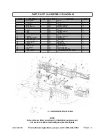
Page 10: ...rse the Cordless Drill in any liquids 5 When storing Always remove the Battery Pack 27 from the Cordless Drill Keep the Cordless Drill and its accessories in a clean dry location and out of childrens reach SKU 92383 For technical questions please call 1 800 444 3353 PAGE 10 PLEASE READ THE FOLLOWING CAREFULLY THE MANUFACTURER AND OR DISTRIBUTOR HAS PROVIDEDTHE PARTS LIST AND ASSEMBLY DIAGRAM IN TH...

Page 11: ...ft Grip 1 25 Screw M 8 x 14 8 5 Left Head Grip 1 26 Right Housing 1 6 M otor Gear 1 27 18V Battery Pack 1 7 Chuck 1 28 Spring 2 8 Shaft 1 29 Screw M 8 x 8 1 9 Bond 1 30 Spring 1 10 Bearing 608 2 31 Socket 2 11 Bearing 1 32 Screw M 6 x 6 1 12 Taper AFC Gear 1 33 Red W ire 1 13 Right Head Grip 1 34 Black W ire 1 14 Taper Gear Shaft 1 35 Nut M 8 1 15 Bearing 627 1 36 Red W ire 1 16 W asher 1 37 Black...

Reviews: