


CON-2
XII.F.
(Continued)
On bellows valves, also install a clean
pipe plug in the bonnet vent connection,
until it is finger tight. The purpose of this
is to obtain the smallest possible leak
path. Remove this plug upon
completion of test.
Examine the following valve components
for leakage during back pressure testing:
a.
The nozzle/base joint.
b.
The adjusting ring pin seal.
c.
The base/bonnet joint.
d.
The bonnet/cap joint.
e.
If conventional valve, the “tight”
bonnet vent plug.
f.
The “loose” bonnet vent plug, if
bellows valve.
Leakage is best detected by application
of a liquid leak detector.
NOTE:
The use of soap, or household
detergent, as a leak detector is not
recommended, as it may bridge small
leaks.
Repair of leaking valve joints may be
attempted by tightening the leaking joint
while the valve is still on the stand. If this
does not stop the leak, tear down and
inspect the leaking joint(s); both the metal
surface(s) and gasket(s).
If the valve internals have been disturbed,
it is necessary to retest in accordance
with the instructions contained in this
manual. Otherwise, repeat the back
pressure tests, as outlined above.
5.
Blowdown Adjustment
Blowdown adjustments are made by
means of the adjusting ring on Type 1900
valves.
If longer or shorter blowdown is required,
it can be obtained as follows:
a.
To increase the blowdown (lower
reseating pressure), the adjusting ring
must be raised by moving the notches,
from left to right, past the ring pin
hole.
Page 38
b.
To decrease the blowdown (raise
reseating pressure), the adjusting ring
must be lowered by moving the
notches, from right to left, past the
ring pin hole.
NOTES:
•
Unless the test stand
capacity is equal to,
or greater than, that
of the valve, do not
attempt to set
blowdown. Simply
return the adjusting
ring to the recom-
mended position.
(Tables 12-14).
•
The valve will not
achieve rated re-
lieving capacity if the
adjusting ring is
positioned too low.
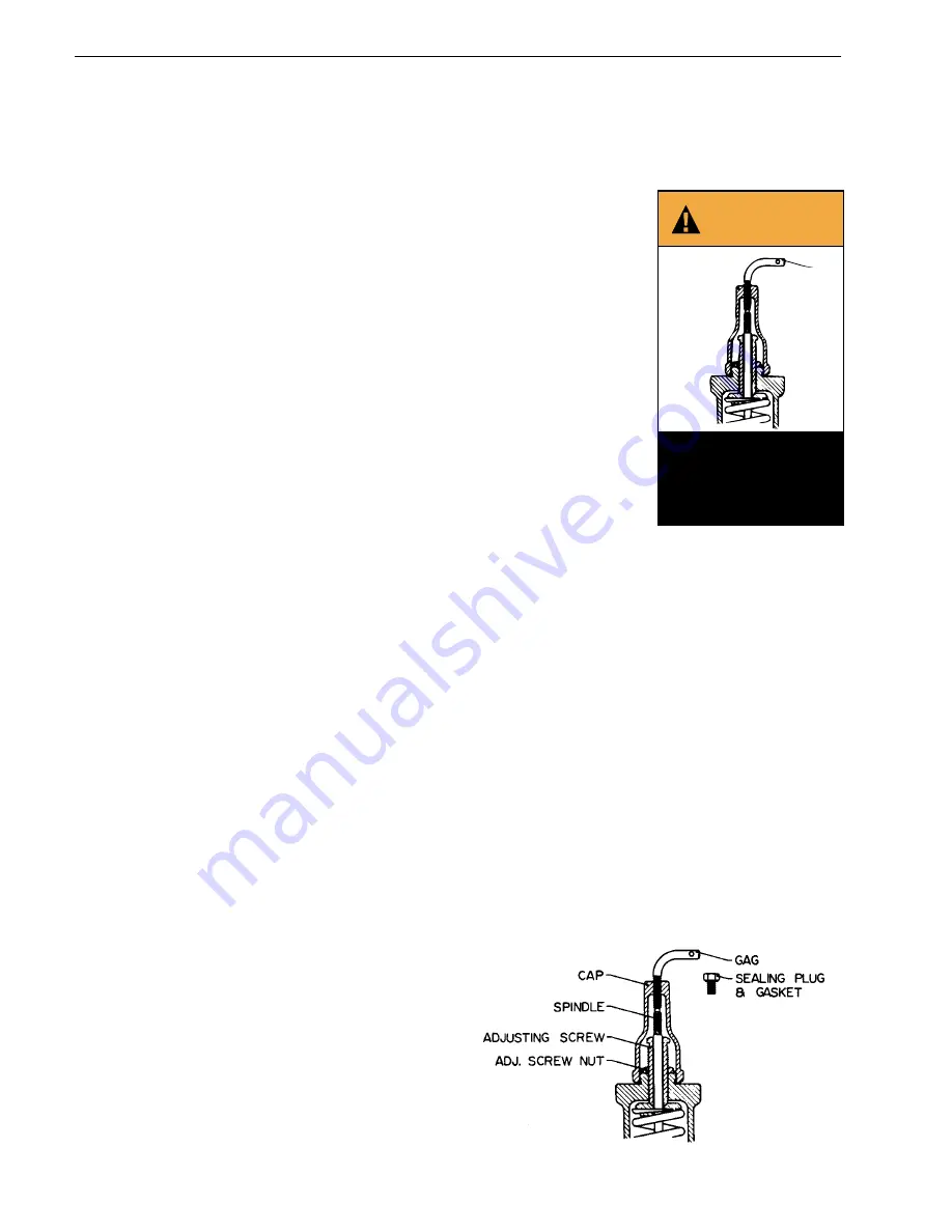
Gag safety valve during
ring adjustments to
avoid possible severe
personal injury or death.
y or death.
GAG
WARNING
FIGURE 37
XIII. Hydrostatic Testing
and Gagging
When hydrostatic tests are required after installation of
a safety relief valve, the safety relief valve should be
removed and replaced with a blind flange, if the
hydrostatic test pressure will not be greater than the
operating pressure of the equipment, a test gag may be
used. Very little force (i.e., fingertight pressure) on the
test gag is sufficient to hold hydrostatic pressures. Too
much force applied to the gag may bend the spindle
and damage the seat. After a hydrostatic test, the gag
must be removed and replaced by the sealing plug
furnished for this purpose. (Test gags for Consolidated
®
Safety Relief Valves can be furnished for all types of
caps and lifting gears.)


