


CON-2
X.H. (Continued)
2.
Machining Procedure: Metal to Metal Seat
See Figure 15, page 15.
a.
Take light cuts across the surface L at 5
°
,
until the damaged areas are removed.
(See Figure 15) Turn to the smoothest
possible finish.
b.
Cut back the outside surface at G, until
dimension N is obtained. The surface at
G is common to all nozzles except the
D-1. Omit this step on the D-1 orifice
nozzles.
c.
Machine bore diameter H, until
dimension E is obtained. Re-establish
angle P.
d.
The nozzle is now ready for lapping.
e.
When the minimum dimension D is
reached, the nozzle should be discarded.
3.
Machining Procedure: O-Ring Seat Seal
See Figure 15, page 15.
a.
Take light cuts across surface A (45
°
),
until the damaged areas are removed.
Turn to the smoothest possible finish.
b.
Cut back the outside surface at M, until
dimension J is obtained.
c.
Machine radius B.
d.
The nozzle is now ready for grinding.
e.
When the minimum dimension D is
reached, the nozzle should be discarded.
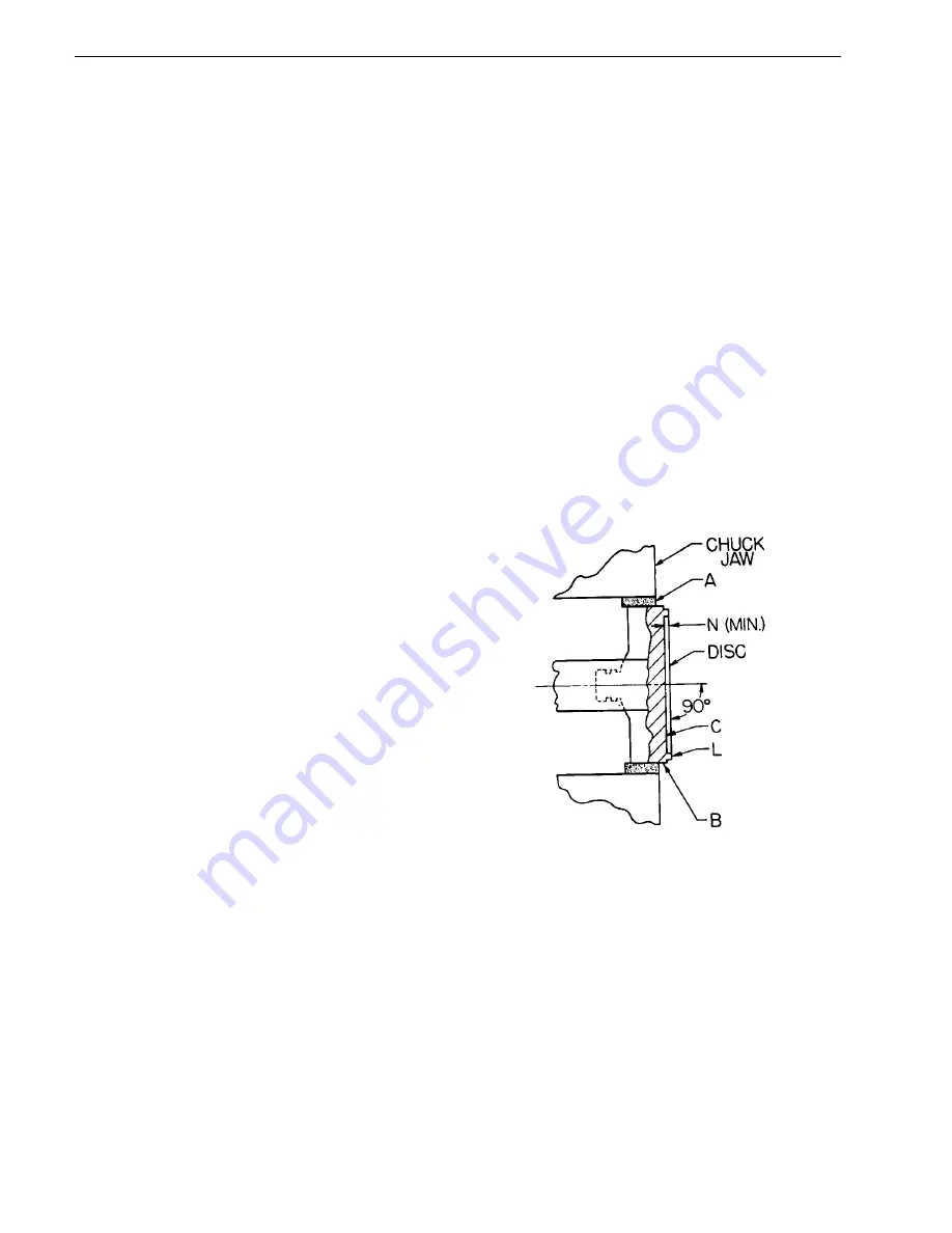
I.
Remachining the Disc Seat*
The standard disc seating surface (see Figure
30) can easily be machined as follows:
1.
Grip the disc in a four-jaw independent chuck
(or collet, if appropriate), using a piece of soft
material such as copper or fiber between the
jaws and the disc as shown at A.
2.
True up the disc so that the surface marked
B and C run true within .001" (0.025 mm),
TIR.
3.
Take light cuts across the seating surface L
until damaged areas are removed. Turn to
smoothest possible finish.
4.
The disc is now ready for lapping.
5.
When the minimum dimension N or T (see
Table 3) is reached the disc should be
discarded. Do not re-establish surface C.
*Thermodisc
®
and O-Ring discs are not to be machined.
FIGURE 30
Page 26


