


CON-2
Approximate Leakage
Maximum
Rate (Standard Cubic
Type of
Manufacturer's
(Bubbles per
Feet per 24 hour)
Valve
Orifice Size
Minute)
Maximum
Conventional F and smaller
40
0.60
G and larger
20
0.30
Balanced
F and smaller
50
0.60
Bellows
G and larger
30
0.45
Page 37
XII.
(Continued)
F. Seat Tightness Testing
1.
General Information
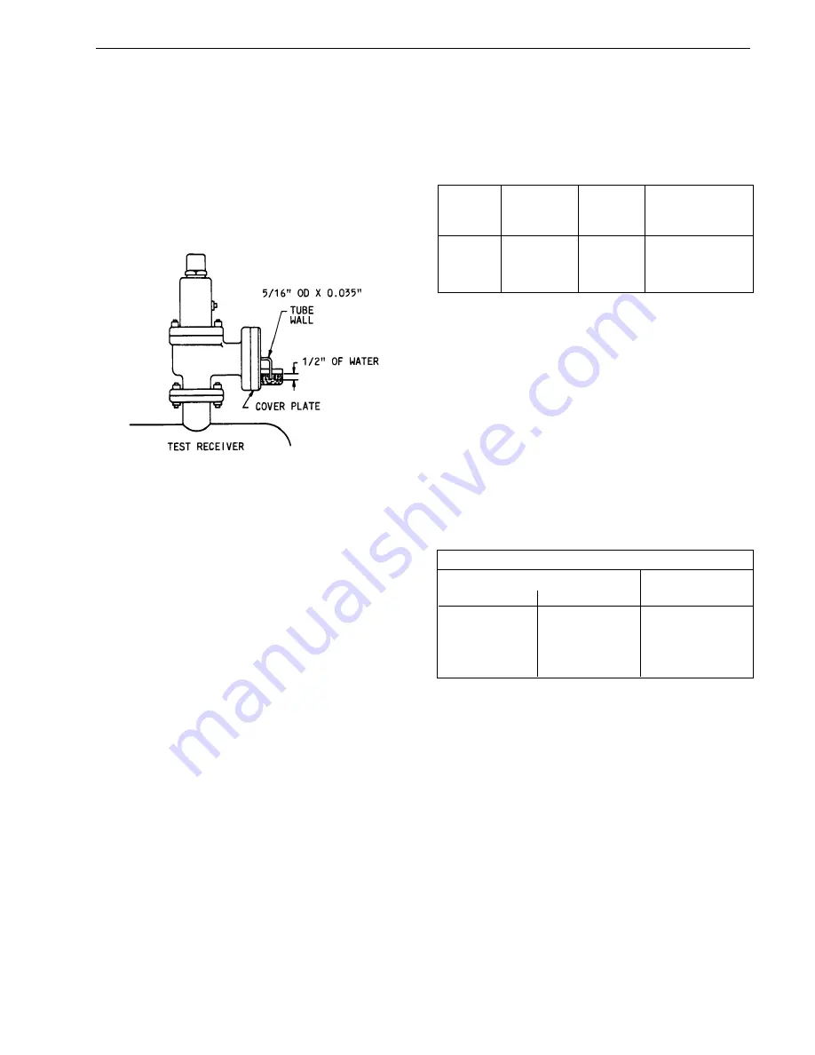
A typical test arrangement for determining seat
tightness for safety relief valves on air or gas
service (in accordance with ANSI B147.1/API
RP 527) is shown in Figure 36.
FIGURE 36
For metal to metal valves, designated for
gaseous service, the leakage rate (in
bubbles per minute) shall not exceed that
shown in Table 17.
TABLE 17
There shall be no visible leakage for
valves designated for steam service (and
tested on steam) or for liquid service (and
tested on water).
3.
Seat Tightness Testing for O-Ring Seat
Seal Valve
The “Tightness Standard’, for O-Ring seat
seal valves shall be no leakage at, or
below, the test pressures shown in Table
18, below.
4.
Recommended Back Pressure Testing
for Joint Leakage
After a given valve has been set for the
correct opening pressure, and if the valve
is to be used in a closed discharge system,
it should be back pressure tested. Testing
can be conducted by installing the cap,
with gasket, and applying air, or nitrogen,
to the base drain connection, or to the
valve outlet. All other openings must be
sealed.
Test pressure should be the greater of 30
psi (2 bar), or the actual valve back
pressure. Air, or nitrogen, pressure should
be held for 3 minutes, before applying
leak detector solution to all connections
(joints).
Set Pressure
Test Pressure
(psig)
(bar)
(% of Set Pressure)
5 to 30
.35 to 2.07
90
31 to 50
2.14 to 3.45
92
51 to 100
3.52 to 6.9
94
100 and above
6.9 and above
95
Seat Tightness Testing for “O” Ring Seat Seals
®
TABLE 18
Leakage measurement shall be made
with the use of a piece of 5/16 in. OD
tubing with 0.035 in. wall. The tube end
shall be cut square and smooth. It shall
also be perpendicular to, and 1/2 in. below,
the surface of the water.
2.
Seat Tightness Testing: Metal to Metal
Seats
With the valve mounted vertically (as
shown in Figure 39 above), the leakage
rate, in bubbles per minute, shall be
determined with pressure at the safety
relief valve inlet, which must be held at 90
percent of the set pressure immediately
after popping. For valves set at 50 psig or
below, the pressure shall be held at 5 psi
below set point. The test pressure shall
be applied for a minimum of 1 min. for
valves on inlet sizes through 2 inches; 2
min. for sizes 2-1/2, 3 and 4 inches; and
5 min. for sizes 6 and 8 inches.


