Andco Eagle Actuator IOM NGS.IPG.0031| 3
In all mounting situations, the final trimming
adjustment of the actuator installation is ±1/8 inch.
NOTICE
8. After Installation the actuator length can be adjusted
+/-1/8 inch
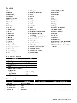
a. Loosen the jam nut (28).
b. Turn the Clevis (29) clockwise to decrease or counter
clockwise to increase the actuators installed length.
Because the thread grip is limited, make sure the clevis (29) is
engaged by a minimum of four threads and that it does not contact
the drive screw (4) when the extension rod (6) is fully retracted.
CAUTION
13. Keep limit switch compartment dry and clean.
To minimize the possibility of condensation damage, it is
suggested that moisture/gas tight conduit seals be installed
at the conduit connections.
14. Dust Ignition Proof Enclosure, Class II, Division 1, Groups E, F
& G.
Indoor and Outdoor Locations.
All actuators provided with dust-ignition proof enclosures must
have properly installed electrical access covers to exclude ignitable
amounts of dust. When reinstalling these covers make sure the
mating seating surfaces and gaskets are clean and the attachment
bolts are securely tightened. If the motor end bell pipe plug has
been removed to adjust the actuator, the pipe plug must be
reinstalled tightly. The actuators must be able to operate at full
rating without developing surface temperatures high enough
to cause excessive dehydration or gradual carbonization of any
organic dust deposits on the actuator enclosure.
The grounding lug on the actuator enclosure exterior must be
wired to a suitable grounding system with a minimum of #10
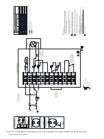
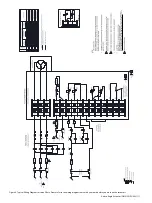
AWG wire as noted in the electric wiring diagram provided with
the actuator.
CAUTION
CONDUCTOR TEMPERATURE RATING
All conductors used for field wiring connections to the actuator
shall carry a rating for a minimum temperature of 90°C.
CAUTION
LIFTING HAZARD
Single person lift could cause injury.
Use assistance when moving or lifting.
CAUTION
VOLTAGE SUPPLY
Verify that the supply voltage to the actuator matches the voltage
on the nameplate (33) on the gear compartment cover (21).
3. To prevent premature wear of the drive nut (7) or extension
rod seal/wiper (2), verify that the alignment between the
actuator mounting support and the driven equipment
places no side loading on the extension rod (6) at any point
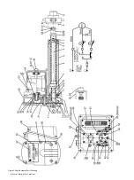
throughout the full stroke length. Refer to Figure 2 on page
7.
4. Do not hammer or gouge the outside surface of the
extension rod (6). This may damage the plating integrity or
cause surface irregularities which can damage rod seals.
5. Face flange or trunnion mounted:
a. Position the body tube adapter (57) to the desired
orientation.
b. Verify that the pins of the trunnion mounting
configuration are parallel with the clevis pin.
c. Tighten the nut and bolt arrangement of the body tube
adapter to 50-55 ft-lbs. of torque.
6. For Clevis mounting: Verify the pins of the Clevis bracket
and for Clevis (29) are parallel.
7. Apply a light film of lubricant to all pinned connections.
ATTENTION
TEMPÉRATURE NOMINALE DES CONDUCTEURS
Tous les conducteurs utilisés pour les raccordements du câblage sur
site de l’actionneur doivent présenter une température nominale
minimum de 90 °C.
ATTENTION
RISQUE LIÉ AU LEVAGE
Le levage de l’unité par une seule personne est dangereux.
Demandez de l’aide lors du déplacement ou du levage de l’unité.
Dans toutes les situations de montage, le réglage final de coupe de
l'installation de l'actionneur est de ±1/8 pouce (3,175 mm).
AVIS
Étant donné que le filetage de la poignée est limité, assurez-vous
que la chape (29) est engagée d'un minimum de quatre filets
et qu'elle ne touche pas la vis d'entraînement (4) lorsque la tige
d'extension (6) est complètement rétractée.
PRUDENCE
PRUDENCE
TENSION D'ALIMENTATION
Vérifier que la tension d'alimentation vers l'actionneur correspond
sur la plaque signalétique (33) du couvercle du compartiment de
l'engrenage (21).
9. Upon completion of all mounting operations verify that
the jam nut (28) is tight, and that all cotter pins have been
secured.
10. The actuator must be installed and wired in accordance
with all local electrical codes and the most current edition
of the National Electrical Code.
11. Grounding connection must be wired to a TN-S, IT (with
insulation monitoring device), or TT (with residual current
device) type grounding system with a minimum of #10
AWG wire. (see below for picture).
12. Route the electrical conduit up into the actuator to prevent
internal condensation from running into the limit switch
compartment.

