4 |Dresser Natural Gas Solutions
5.0 Electrical and Functional tests
Functional Test:
1. Unit ratings (voltage, speed, stroke, options, etc) are to be
confirmed with the Sales Order.
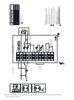
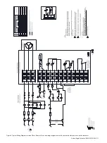
2. Wiring is to be confirmed through continuity tests refenced
from the assigned wiring diagram. Electrical connections
and components are to be secure.
3. Unit is to be run in both directions through the full rated
stroke. Unit should operate smoothly without unusual noise
or vibration.
4. Unit housing is to be visually inspected for mechanical
soundness and esthetics.
WARNING
MOVING PARTS
Internal moving parts. Pinch point
hazard. Keep hands clear during
operation.
WARNING
HAZARDOUS VOLTAGE
Disconnect all electrical power to the actuator prior to performing
any service or maintenance. Unit may have more than one live
circuit. Refer to wiring diagram supplied with unit.
CAUTION
BURN HAZARD
Possible hot surfaces. Keep hands clear of surface. Allow surface to
cool before performing any maintenance.
Disconnect all electrical power to the actuator prior to removing
the limit switch compartment cover and performing any setting
adjustments. Unit may have more than one live circuit. Refer to
wiring diagram supplied with unit.
WARNING
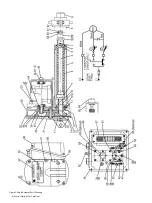
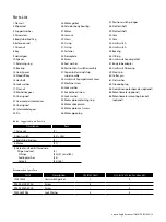
1. Remove the limit switch compartment cover (38) to gain
access to the position switch assembly.
2. Remove the motor pipe plug (46) for access to slot “A”
located in the end of motor shaft.
3. With a manual or power screw driver rotate the motor shaft
in a clockwise direction to extend or counterclockwise
direction to retract the extension rod.
4. To set the extend limit switch, turn the motor shaft in a
clockwise direction. Note the direction the slotted shaft (48)
is turning while extending extension rod to its
desired position.
5. Depress the position switch plunger (47) and turn the
slotted shaft (48) in the same direction it was turning as in
step 4 and continue to turn in this
direction until the cam (50) flat comes in contact with the
limit switch (52) lever.
6. Repeat steps 4 and 5 to set the retract limit switch utilizing
the slotted shaft (49), limit switch (53) and cam (51). Turn
the motor shaft in a counterclockwise direction.
7. Replace the motor pipe plug (46).
8. Replace the limit switch compartment cover (38).
9. Re-energize electrical power to the actuator.
If damaged, replace the complete geared position limit switch
assembly rather than attempting field repair.
NOTICE
En cas de dommage, remplacer l’assemblage complet de
l’interrupteur de fin de course du train d’engrenages plutôt que de
tenter une réparation sur place.
AVIS
Débranchez tous les câbles électriques de l'actionneur avant de retirer
le couvercle du compartiment de l'interrupteur de fin de course et de
procéder aux réglages. L'unité peut avoir plus d'un circuit sous tension.
Reportez-vous au schéma de câblage fourni avec l'appareil.
AVERTISSEMENT
ATTENTION
RISQUE DE BRÛLURE
La surface risque de devenir chaude. Éloignez vos mains de
la surface. Laissez refroidir la surface avant les travaux de
maintenance.
AVERTISSEMENT
PIÈCES MOBILES
Pièces mobiles internes.
Risque de point de pincement.
Tenez vos mains éloignées
pendant le fonctionnement.
AVERTISSEMENT
TENSION DANGEREUSE
Débranchez l'alimentation électrique de l'actionneur avant
d'effectuer une réparation ou un entretien. L'unité peut avoir plus
d'un circuit sous tension. Reportez-vous au schéma de câblage
fourni avec l'appareil.
4.0 Geared Position Limit Switch
Adjustment
The geared position limit switches have been preset at the
factory to trip and interrupt the electric control for the extend and
retract positions according to specified stroke. Final limit switch
adjustment must be done at installation. Set the extended and
retract limit switches to the positions required per the application,
the setting is to be done in accordance with the following
procedure.
CAUTION
BURN HAZARD
Possible hot surfaces. Keep hands clear of surface. Allow surface to
cool before performing any maintenance.
ATTENTION
RISQUE DE BRÛLURE
La surface risque de devenir chaude. Éloignez vos mains de
la surface. Laissez refroidir la surface avant les travaux de
maintenance.

