


5.0 APPENDIX
36
R699751 - DreamScaler3 User Manual
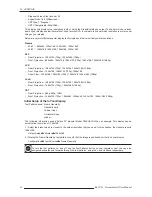
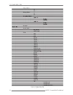
The ‘Vertical Lines’ test pattern should appear as one pixel wide black and white columns. If you see any irregular
pattern(s) in the image, you know that the display is scaling the signal horizontally. To override the internal scaling,
adjust the horizontal size of the image to see if the test pattern can be displayed correctly.
Output Setup
⇒
⇒
⇒
⇒
Format
⇒
⇒
⇒
⇒
User
⇒
⇒
⇒
⇒
H-Size
⇒
⇒
⇒
⇒
Adjust
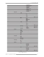
The ‘Horizontal Lines’ test pattern should appear as one pixel tall black and white rows. If you see any irregular
pattern(s) in the image then you know that the display is scaling the signal vertically. To override the internal scaling,
adjust the vertical size of the image to see if the test pattern can be displayed correctly.
Output Setup
⇒
⇒
⇒
⇒
Format
⇒
⇒
⇒
⇒
User
⇒
⇒
⇒
⇒
V-Size
⇒
⇒
⇒
⇒
Adjust
The ‘Judder’ test pattern displays a bar that bounces back and forth at the chosen output frequency selected in the
‘framerate’ parameter. When this test pattern is displayed correctly, the bar moves smoothly across the screen and
bounces from side to side.
When this pattern is displayed incorrectly, this bar may ‘tear’ as it moves across the screen. To adjust the framerate
conversion, go to the ‘Output Setup’ menu.
For displays that will only display 50Hz (PAL)
Output Setup
⇒
⇒
⇒
⇒
Framerate
⇒
⇒
⇒
⇒
50Hz
⇒
⇒
⇒
⇒
50Hz Lock
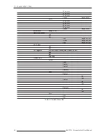
Output Setup
⇒
⇒
⇒
⇒
Framerate
⇒
⇒
⇒
⇒
60Hz
⇒
⇒
⇒
⇒
Unlock
⇒
⇒
⇒
⇒
50.00
For displays that will only display 60Hz (NTSC)
Output Setup
⇒
⇒
⇒
⇒
Framerate
⇒
⇒
⇒
⇒
50Hz
⇒
⇒
⇒
⇒
Unlock
⇒
⇒
⇒
⇒
59.94
Output Setup
⇒
⇒
⇒
⇒
Framerate
⇒
⇒
⇒
⇒
60Hz
⇒
⇒
⇒
⇒
60Hz Lock
Display Calibration
Test Patterns Used:
Brightness/Contrast
Color8 Bars75
Color8 Bars100
Gray Ramp
The DreamScaler3 has several test patterns to assist in the setup of your display. Adjustments should be made on
your display, not on the DreamScaler3, to correctly setup your DreamScaler3 and display.
The ‘Brightness/Contrast’ test pattern will assist you in setting up both the brightness (black level) and contrast
(white level) of your display. The ‘Brightness/Contrast’ test pattern is composed of 4 quarter-screen blocks. Two of
the blocks have a background level of standard black and the other two blocks have a background level of standard
white. Embedded in the black blocks are 3 bars.
One is 4 IRE below black (blacker-than-black), one is 1 IRE above black, and the third is 2 IRE above black.
Embedded in the white blocks are 3 bars. One is 1 IRE above white (whiter-then-white), one is 1 IRE below white,
and the third is 2 IRE below white. The bottom two blocks differ slightly from these levels. For the bottom two blocks,
the blacker-than-black is at the lowest possible luma level and the whiter-than-white bar is at the highest possible
luma level. When the brightness and contrast are adjusted correctly, you should be able to see the 1 IRE and 2 IRE
above black bars on the black background and the 1 IRE and 2 IRE below white bars should be visible on the white
background. When the brightness is adjusted correctly, black objects should appear ‘black’ with the details still intact
and lighter areas should be ‘light’, not gray, with the details still intact. When the contrast is adjusted correctly, white
objects will appear ‘white’ with the details still intact. Because the contrast settings can affect brightness settings we
recommend that you check the brightness setting after making this adjustment.
The ‘Color8 Bars75’ and ‘Color8 Bars100’ will assist in setting up the saturation (color) and hue (tint) of your display.
The ‘Color8 Bars75’ test pattern consists of 8 vertical bars across the screen at a 75% saturation level. The ‘Color8
Bars100’ test pattern consists of 8 vertical bars across the screen at a 100% saturation level. From left to right the
Note:
If you have a CRT based display, following the instructions above may yield a contrast setting too high. If the
contrast is set too high, you will get blooming and loss of details in the highlighted areas. It is more helpful to use the
two vertical lines in the test pattern. Adjust the contrast up and down and you will notice that these lines will bend as
you increase the contrast. To properly adjust contrast on a CRT based display, decrease the contrast until the
vertical lines start to straighten out. If possible, the two lines should be straight. On some CRT, the lines may not
straighten even if you turn the contrast to its minimum. If this is the case, slowly increase the contrast to a point just
before the vertical lines have extreme bending. You have now properly set up the contrast of your display. Continue
to set up brightness as detailed above.