Dr Robot Jaguar V4 User Manual Download Page 9


Copyright © 2014, Dr Robot Inc.  All Rights Reserved.    www.DrRobot.com                   V.04.11.14                   

- 9 - 

Operation Scenario  

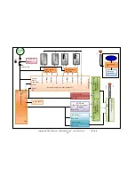
Diagram below illustrates the typical operation scenario. The Jaguar is a wireless networked outdoor mobile 
robot. It comes with a wireless 802.11 AP/router. The remote host controller PC running the “Jaguar Control” 
program connects to the Jaguar robot via: 


Network cable – Connect the robot on-board AP/router. (DO NOT connect to the WAN port), or 


Wireless – To connect the host controller PC to the on-robot wireless AP/router, configure the host PC’s 
wireless settings using the default wireless configuration settings found in the Network Connection 
session of this manual. 

Human operator carrying the host controller PC could use the head-mounted display (accessory option) and the 
included game-pad controller in outdoor environment to monitor and control the operator under any outdoor 
lighting environment, even under direct sunshine.  The included “Jaguar Control” program will therefore be 
projected on the head-mounted display, where you could see all the sensor information from the robot, and the 
video streamed from the camera on robot (Please refer to “Jaguar Control program” session for detail). 


Typical Operation Scenario 

Note: The host controller PC running the “Jaguar Control” program could be mounted on the robot instead off the 
robot if your application requires so.  

Software Installation 

Jaguar Control programs, application development library and supporting documents could be found from the 
Jaguar software CD. 

On the host controller computer, you should install the following programs from the installation CD: 


“Jaguar Control” program -  installed  by the Setup.exe from CD 


Google Earth program - could be downloaded from http://earth.google.com/download-

earth.html. Please follow its installation instruction. 

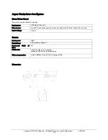
Portable PC (Host controller PC) 
(Optional) 

Head-mounted display 
(Optional) 

Gamepad 

Controller

Summary of Contents for Jaguar V4

Page 1: ...Copyright 2014 DrRobotInc AllRightsReserved www DrRobot com V 04 11 14 All Terrain Autonomous Navigation Robot with GPS IMU JaguarV4 withManipulatorArm UserGuide...

Page 2: ...r draining the battery such as keeping the robot on without charging will damage the battery Neverpositionyourfinger s inbetweenthetrackand orarm smovingparts evenwhenthepowerisoff Therobotarmsmustbep...

Page 3: ...re solely owned and copyrighted by Dr Robot End users are authorized to use for personal research and educational use only Duplication distribution reverse engineering or commercial application of the...

Page 4: ...Overlook 8 Operation Scenario 9 Software Installation 9 III Operation of Jaguar Robot 10 Turn on off the Platform 10 Using Dr Robot Jaguar Control Program 10 Recharging 15 IV Hardware and Electronics...

Page 5: ...s an articulated sensor platform Integrated software features independent joint space control as well as gripper Cartesian space control While it only has 3 rotation joints excluding gripper when work...

Page 6: ...ensing controller PWM Position and Speed Control 5Hz GPS and 9 DOF IMU Gyro Accelerometer Compass Laser scanner 5 6m 4m or 30m Optional Temperature sensing Voltage monitoring Headlights Color Camera 6...

Page 7: ...eless Module 2 DMD2500 25A peak 50A Dual channel DC Motor Driver Module 2 PMCHR12 DC DC Power Board 1 AXCAM A 640x480 Networked Color Camera max 30fps with Two Way Audio 1 OGPS501 Outdoor GPS Receiver...

Page 8: ...ow illustrates the key components that you will identify on the Jaguar robot Jaguar V4 with Manipulator Arm Platform Power Switch WiFi Antenna Handle Bar Joint 2 Camera Laser Scanner Optional Headligh...

Page 9: ...the operator under any outdoor lighting environment even under direct sunshine The included Jaguar Control program will therefore be projected on the head mounted display where you could see all the...

Page 10: ...ntrol and navigate the Jaguar move the arm tracks and how to interpret process display and log multi sensor information This program is provided with source code c updates motor encoder reading motor...

Page 11: ...is the location you would like the map to center and show around You should modify this location according to your location This could be done by inputting the value in this xml file or navigating on...

Page 12: ...rack position After powering up the robot or when the actual arm position is different from the arm position window shown on the right you should reset the arm track position as following drive the ar...

Page 13: ...it will display laser scanner data in polar view as shown below Click Turn on and then Scan button You could use trackbar to adjust the data cut off distance i e any obstacle with distance larger tha...

Page 14: ...otors Arm Driver1 tab will display motor driver controller 1 states for Joint 1 and 2 If you did not get the sensor reading back you could click QueryCmd button to send query command Please make sure...

Page 15: ...s type of battery explosion and damage could occur Please read the Charge Station manual first and follow all the safety rules before proceeding further 1 Turn off the robot 2 Loose the locking screws...

Page 16: ...nnected to its power supply For more detail about charger station operation warning and error message maintenance and safety message please refer to Intelligent Digital Balance Charger Operation Manua...

Page 17: ...Camera 192 168 0 65 Port 8081 User ID root Password drrobot Manipulator Arm Camera 192 168 0 64 Port 8082 User ID root Password drrobot Advanced Network Settings You could also change the Wireless AP...

Page 18: ...V Temperature Head Light Control Motion Sensing Controller Jaguar Ver Ethernet Module 1 Port 10001 Port 10002 Power 3 3V Ethernet Module 2 Port 10001 Port 10002 Power 3 3V Laser Scanner 9 DOF IMU Gyro...

Page 19: ...Channel 0 for left and right arm track Channel 3 4 for left and right track wheel Board voltage measuring Battery voltage measuring Motor temperature measuring 3 units Other extended A D channels plea...

Page 20: ...available one with measurement range of 0 02 4m and other one is 0 1 30m Input power 5V Detectable range 0 02 4m Accuracy 0 02 to 1m 10mm 1 to 4m 1 Measurement Resolution 1mm Angular Resolution appro...

Page 21: ...ower H Bridge 2 channels Max current up to 10A continuous power per channel peak up to 20A per channel for a minute Input voltage 7 30V Camera Input power 48V Resolutions 720x480 to 176x120 Horizontal...

Page 22: ...pulley belt speed reduction 34 20 the motor shaft encoder resolution is 722 counts per revolution Further Development Programming The Jaguar Control program The Jaguar Control program is written with...

Page 23: ...ar GetMotorPWMValue1 here is front left arm encoder reading armMotor 0 encoderDir myJaguar GetEncoderDir1 armMotor 0 encoderPos myJaguar GetEncoderPulse1 armMotor 0 encodeSpeed myJaguar GetEncoderSpee...

Page 24: ...84 16384 16384 To control arm motor using PWM control with value 32767 full PWM you could use myJaguar DcMotorPwmNonTimeCtrAll 32767 NOCONTROL NOCONTROL NOCONTROL NOCONTROL NOCONTROL or myJaguar DcMot...

Page 25: ...t 2 after voltage level conversion You could access the sensor data via TCP socket at port 10002 with IP 192 168 0 61 Default settings for the serial port are 115200 8 N 1 no flow control TCP port num...

Page 26: ...ode 3 For example Command PR 1 200 r It will drive this joint up Command PR 1 200 r It will drive this joint down Command P 1 250 r It will drive this motor to encoder position 250 make sure you know...

Page 27: ...solution 756 2 PI This joint is working in open loop control mode mode 0 For example Command G 2 200 r It will drive Gripper close Command G 2 200 r It will drive Gripper open Command G 2 0 r It will...

Reviews: