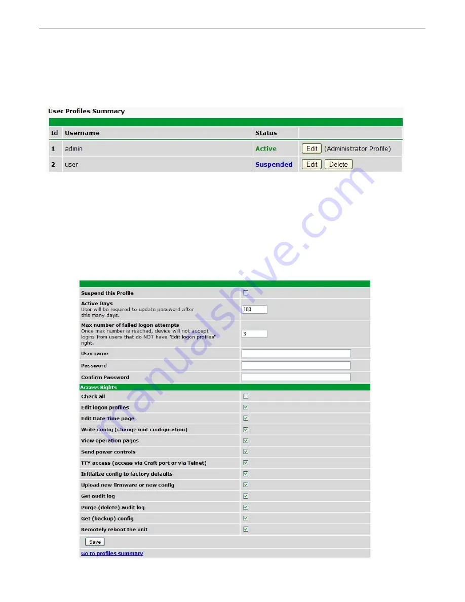
background image

30

6.3.2

User Profiles

Clicking 

User Profiles

 gives you access to modify the default username and password, and to edit the

administrator profile and create up to 9 additional unique user profiles, each with different access rights
to the Remote Power Switch.

The User Profiles screen shows you at a glance whether a profile is active, suspended, or not yet

configured

To create or edit any the 10 user profiles (including the default), click the 

Edit 

button.   

The Administrator Profile:

The first user profile in the User Profiles menu is the Administrator's Profile.  Access rights for the
administrator's profile are all enabled and may not be disabled, nor can the profile be deleted or
suspended.  This is a precaution to prevent a situation in which an access right is disabled for all users.
 You may still edit the 

Username, Password, and Active Days

 fields for the Administrator Profile.

Summary of Contents for RPS AB6

Page 1: ...USER MANUAL Remote Power Switch AB6 February 6 2017 Visit our website at www dpstelecom com for the latest PDFmanual and FAQs D UM RSPDC 12011 Firmware Version 1 0C...

Page 2: ...ein or consequential damages in connection with the furnishing performance or use of this manual Notice Revision History February 23 2017 February 6 2017 November 18 2015 June 18 2015 April 4 2013 Nov...

Page 3: ...ker Switches 3 4 12 Fuses 3 5 13 Alarm Monitoring 4 14 Discrete Alarms 4 1 14 Analog Alarms 4 2 15 Switching Analog Alarms to Current Operation 4 2 1 16 D Wire Sensor Input 4 3 17 Control Relay Connec...

Page 4: ...47 Power Control Provisioning 6 3 12 48 6 3 12 1 Low Voltage Disconnect System Alarms Provisioning 6 3 13 50 Timers 6 3 14 52 Date Time 6 3 15 53 6 3 15 1 Testing your Automatic Time Adjustment NTP S...

Page 5: ...ver have to make a trip out to a site to flip a switch again Specifications 1 1 Power Inputs 2 Studded Terminal Block inputs Voltage 48 VDC 36 to 60 VDC feeds studded terminal blocks Current Draw 350m...

Page 6: ...2 Windows Compatibility XP Vista 7 32 64 bit RoHS 5 Approved...

Page 7: ...nd call DPS Telecom at 800 622 3314 Shipping List Remote Power Switch AB6 D PK RSPDC RPS AB6 User Manual D UM RSPDC 12011 RPS AB6 Resource CD includes manuals MIBs and software DB9M DB9F Download Cabl...

Page 8: ...mp Fuse x4 2 741 05000 00 Nut With Star Washer x9 2 002 01421 00 Studded Power Block Cover x2 2 820 73175 01 Cable Ties x4 1 012 00106 00 Optional Accessories D Wire Temperature Sensor D PK DSNSR 1200...

Page 9: ...river 7 16 Nut Driver Mounting 2 2 The RPS AB6 with 23 rack ear in flush mount position The Remote Power Switch mounts in a 19 rack or a 23 rack using the appropriate rack ears for each size Attach th...

Page 10: ...efore the power input connections can be made the studded power block covers will need to be removed To do this use the DPS Standard No 2 screwdriver Use the leverage provided by the screwdriver to li...

Page 11: ...efore connecting power feeds make sure that the breaker for the power feed you re connecting is switched off 1 Use the grounding lug to connect the unit to earth ground The grounding lug is next to th...

Page 12: ...pin plug connectors 3 per connector For each output feed the 48V cable will be on the left and the ground cable GND will be on the right Power output connectors on the RPS AB6 To connect your power fe...

Page 13: ...terminal 4 Connect the 48V cable to the left terminal for each power output using a small flathead screwdriver tighten the 48V terminal A fully wired output connector 5 Once you ve wired your equipmen...

Page 14: ...accessible Once you ve wired power inputs and outputs to the unit you can perform all other operations from the unit s front panel The front panel of the RPS AB6 Front Panel LEDs 3 1 Indicator LEDs fo...

Page 15: ...feed is powered 100BT Solid Green 100 BT connection Off 10 BT connection Status Blink Red Bootloader application is active the unit is starting up Blink Green The main application is active Breaker A...

Page 16: ...corresponding power inputs on the backside of the unit Use each switch to effectively turn on or off the power feeds on either side of the unit Note When turning on power using a breaker switch the co...

Page 17: ...e not required The user should choose fuses rated to fit their application and should not exceed 40 Amps worth of fuses per 6 output side Aor B Fuse alarm LEDs are located above the fuses to visually...

Page 18: ...referenced to ground The ground side of each alarm point is internally wired to ground so alarm points can either connect as a dry contact or a contact to ground In a dry contact alarm the alarm lead...

Page 19: ...the analog channels is 90 to 90 VDC or 4 to 20 mA You can connect analog alarm inputs to the RPS AB6 by using the 8 pin analog alarm connectors For the 8 pin analog connector s pinout information see...

Page 20: ...depowered and disconnected from all network connections 2 Remove the screws from the sides of the RPS AB6 case 3 Slide off the top cover of the case to expose the circuit board 4 The adjustable jumper...

Page 21: ...16 D Wire sensors The RPS AB6 powers and communicates with your D Wire sensors via straight through RJ 11 cables Connecting D Wire Sensors Using a 6P4C straight through RJ 11 cable part D PR 045 10A...

Page 22: ...ue 99 1 38 64 Display 6 User Analog 3 alarms 99 1 1 5 User Analog 3 value 99 1 6 32 User Analog 4 alarms 99 1 33 37 User Analog 4 value 99 1 38 64 Display 7 User Analog 5 alarms 99 1 1 5 User Analog 5...

Page 23: ...9 1 38 64 Display 14 Digital Sensor 11 alarms 99 1 1 5 Digital Sensor 11 value 99 1 6 32 Digital Sensor 12 alarms 99 1 33 37 Digital Sensor 12 value 99 1 38 64 Display 15 Digital Sensor 13 alarms 99 1...

Page 24: ...ocally interface with the RPS however some advanced configuration monitoring and control options may not be available via TTY For more advanced options use the RPS s secure web browser interface Conne...

Page 25: ...ormation Username admin Password dpstelecom See Ethernet Configuration later in this chapter to continue configuring your Remote Power Switch s ethernet port 5 1 1 Control Power via TTY After you have...

Page 26: ...urning it back on again Print Summary P View a list of relay states and fuse statuses ESC Go back to the previous menu Connecting via LAN 5 2 Ethernet port If you have physical access to the Remote Po...

Page 27: ...y have to reboot your PC to apply your changes 4 Once the IP address and subnet mask of your computer coincide with the Remote Power Switch s you can access the Remote Power Switch via a Telnet sessio...

Page 28: ...or the C onfig menu 2 Press E for the E thernet menu 3 Configure the Unit s address Subnet mask and default Gateway 4 Press ESC to escape to the Ethernet menu 5 Press B to perform a soft reboot of the...

Page 29: ...a means to circumvent the firewall in the event that your whitelist blacklist blocks legitimate users out of the unit s web interface To configure the unit s web interface visit the Firewall section...

Page 30: ...elated to the Remote Power Switch Web Interface are based on firmware version 1 0 Instructions and images may differ from later versions of the Remote Power Switch firmware Logging in to the Web Inter...

Page 31: ...terface is split into 3 sections The blue Operation menus provide access to monitor and control your power feeds The green Provisioning menus are where you ll configure your unit alarm thresholds and...

Page 32: ...anges locally The web interface will then prompt you to either Write your changes to the unit or Reboot the unit for changes to take effect in the top left corner of your browser The relevant options...

Page 33: ...this Remote Power Switch Optional field Legal Warning If not blank the text in this field will popup after every login DCP Responder Settings For use with T Mon DCP over LAN Enables DCP transmissions...

Page 34: ...ded or not yet configured To create or edit any the 10 user profiles including the default click the Edit button The Administrator Profile The first user profile in the User Profiles menu is the Admin...

Page 35: ...server Write Config Change Unit Configuration Enables the user to change the unit config by accessing the Write feature in the control menu View Operation Pages Allows the user to access Operation men...

Page 36: ...32 also navigate away from the user profiles screen at any time by clicking any of the menu options on the left side of the screen...

Page 37: ...assigned an IP address from your DHCP server The IP you ve already assigned to the unit becomes inactive Using DHCP means the unit will NOT operate in a T Mon environment Unit IP IP address of the Re...

Page 38: ...ist Allow only enabled entries puts the firewall in White List Mode allowing only IP addresses subnet masks in the Firewall Entries list to access the Remote Power Switch In the Firewall Entries secti...

Page 39: ...le i e for HTTP set both port fields to 80 HTTP operates on port 80 for Telnet block port 2002 for HTTPS block port 443 3 Change both the Network Mask fields to 0 0 0 0 This tells the the AB6 to block...

Page 40: ...36 6 3 5 SNMP From the SNMP menu you can configure SNMP Configure SNMP settings for up to 3 users...

Page 41: ...SNMPv3 User profiles Username The name of the user for which an SNMPv3 management operation is performed Auth Type This identifies the security modes available when SNMPv3 is utilized The modes are a...

Page 42: ...e field shows the type of notification being sent The Remote Power Switch is capable of sending Email notification or SNMP Traps when events occur The Details field shows the server being used for SNM...

Page 43: ...al The email address that the Remote Power Switch will send all email notifications from The address in this field applies to all email notifications Changing the From email address for any one email...

Page 44: ...P TRAP requests Trap Type Indicate whether you would like to send SNMPv1 v2c or v3 traps SNMPv3 user Choose the SNMP user from the drop down box SNMP users are configured from the SNMP menu 6 3 6 3 Sc...

Page 45: ...set If the Notification 1 8 failed alarm displays as in the example below the state shows Alarm in red then your notification settings are incorrect If the Notification 1 8 failed alarm state displays...

Page 46: ...input alarms All thresholds are listed in Voltage MjU indicates a Major Under alarm low voltage The default value is 40Vdc MnU indicates a Minor Under alarm low voltage The default value is 45Vdc MnO...

Page 47: ...ion The Provisioning Alarms menu Basic Alarm Configuration ID Alarm ID number Description User definable description for the discrete alarm point Rev Reverse Reverse Check this box to reverse the pola...

Page 48: ...d designate them to a notification device s The Provisioning Controls screen Basic Controls Configuration ID ID number for the control relay Description User definable description for the NetGuardian...

Page 49: ...t to 1 3 1 4 1 5 _AN D 1 3 5 D2 6 _OR D3 7 is logically equivalent to 1 3 1 4 1 5 2 6 3 7 _OR D01 03 05 D02 06 _AN D02 07 D03 10 12 is logically equivalent to 1 3 1 4 1 5 2 6 2 7 3 10 3 12 _AN D1 3 5D...

Page 50: ...e or below a threshold in order to cause an alarm On Set User definable description condition that will appear for the temperature alarm on Set Example Alarm On Clear User definable description condit...

Page 51: ...Enter values for Major Under MjU Minor Under MnU Minor Over MnO and Major Over MjO 6 3 11 Sensors Provisioning The RPS AB6 supports up to 16 daisy chained D Wire sensors via its D Wire input Sensors c...

Page 52: ...notification device s 1 through 8 you want to send alarm notifications for that alarm point Advanced Sensor Configuration Details Record Freq The amount of time in minutes min or seconds s between eac...

Page 53: ...the unit or flipping the breaker switch associated with a power output Valid options are On Off or Last State which causes the output to revert to the state it was in when the unit lost power Power o...

Page 54: ...t feeds and set individual thresholds for each feed If the input voltage rises above the on threshold for multiple output feeds simultaneously the your remote power switch will honor the appropriate p...

Page 55: ...51 the ID column of the Notifications screen Toggle the checkboxes to determine which notifications you would like sent for each point...

Page 56: ...rs Web refresh How often the web browser is refreshed when in monitor mode Timed Tick The hearbeat function that can be used by masters who don t perform integrity checks Power on Relay Delay Sets the...

Page 57: ...t hour minutes and time of day fro the drop down menus Automatic Time Adjustment NTP Enable NTP Check this box to enable Network Time Protocol NTP Server Address or Host Name Enter the NTP server s IP...

Page 58: ...Test NTP button allows you to check your Network Time Settings 2 Go to the System Alarms page and see if the NTP Failed alarm has set If the NTP failed alarm displays as in the example below the state...

Page 59: ...ption 6 4 1 Power Feed Status Operation From the blue Power Feed Status option under the Operation menu you can check the status of your input feeds The Inputs screen shows when you have an input alar...

Page 60: ...y or may not be present at the output depending on the state of the fuse The On Off and Reset buttons allow you to operate individual power feeds On turns power on Off turns power off Reset temporaril...

Page 61: ...tatus will appear in red if an alarm has been activated The status will be displayed in green when the alarm condition is not present The Default text for an alarm is Alarm This can be configured and...

Page 62: ...ID number for the control relay Description Description for the NetGuardian s control relay defined in the Provisioning Controls menu State Status of the control relay Can either be Released or Latche...

Page 63: ...in ID 1 will refer to the RPS AB6 s internal temperature The internal temperature sensor measures a range of 40 F to 180 F 40 C to 82 2 C within an accuracy of about 2 Basic configuration for the RPS...

Page 64: ...Clear on a light green background as displayed in the example above Note If you checked the Silence checkbox for an alarm on the Provisioning System Alarms page its state will always show Clear on the...

Page 65: ...an be either Alarm or Clear PRef Point reference shows the display and point of the alarm Description Alarm description Device Access 6 5 The Device Access options listed in pink on the left side of t...

Page 66: ...ch Updating Firmware 6 6 To update the Remote Power Switch s firmware 1 click Upload in the upper right corner of the web interface Click Upload in the upper right corner of the web interface to uploa...

Page 67: ...group of 64 alarm points A port is traditionally the actual physical serial port through which the monitoring device collects data The address is a number representing the monitored device The terms p...

Page 68: ...ormation when you call our Technical Support representatives can assist you in gathering it Please write the information down for easy access Please have your user manual and hardware serial number re...

Page 69: ...old it harmless for and against any and all claims damages losses costs expenses obligations liabilities fees and costs and all amounts paid in settlement of any claim action or suit which may be asse...

Page 70: ...66...

Page 71: ......

Page 72: ......

Page 73: ...r lightning unless and to the extent that the product specification provides for resistance to a defined disaster e damage caused by unauthorized attachments or modifications f damage during shipment...

Page 74: ...Product manuals Product datasheets Exclusive user forms Expert tips on using your alarm monitoring equipment advanced techniques that will save you hours of work Educational White Papers deliver fast...

Reviews: