MPU00013EN, V05
N24140011
www.durr.com
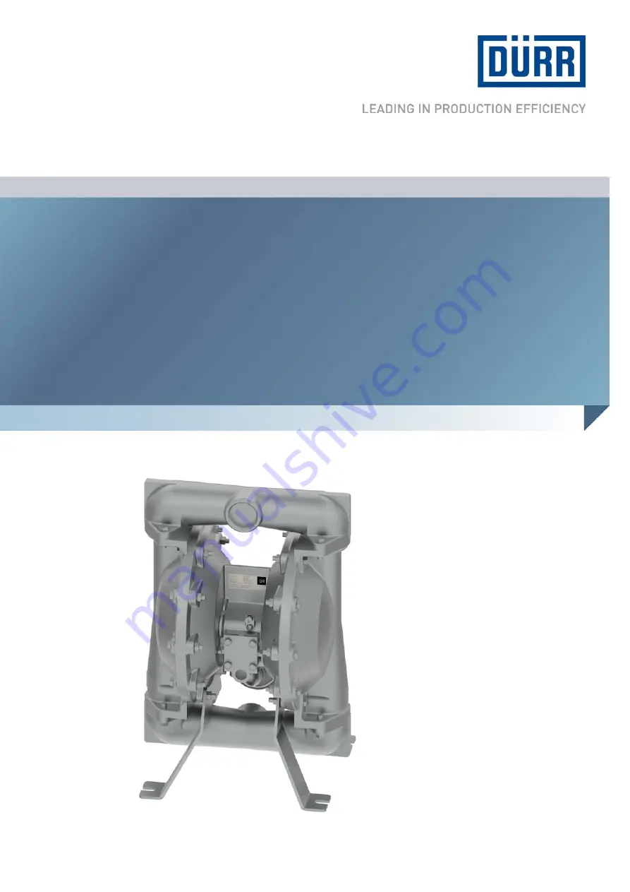
EcoPump ADAir Operated Diaphragm Pump
Operation manual
Page 1: ...MPU00013EN V05 N24140011 www durr com EcoPump AD Air Operated Diaphragm Pump Operation manual ...
Page 2: ...eim Bissingen Germany Phone 49 0 7142 78 0 Internet www durr com The reproduction and distribution of this document use and communication of its contents are not permitted without express written approval Offenders will be liable for damages All rights reserved in the event of the grant of a patent or utility model 01 2020 EcoPump AD MPU00013EN 2 36 ...
Page 3: ... documentation Always follow safety instructions handling instructions and specifications of every kind Illustrations can deviate from the technical con struction Validity range of the document The scope of the document is as follows N24140011 EcoPump AD 2420 8 SST 1 1 2 Hotline and Contact If you have queries or would like technical informa tion please contact your dealer or sales partner 01 2020...
Page 4: ...lush the pump 14 8 Cleaning 15 8 1 Safety recommendations 15 8 2 Cleaning 15 9 Maintenance 15 9 1 Safety recommendations 15 9 2 Maintenance schedule 16 9 3 Dismantle and assemble 16 9 3 1 General notes 16 9 3 2 Dismantle inlet and outlet mani fold 17 9 3 3 Dismantle material assembly 17 9 3 4 Dismantle pneumatic assembly 18 9 3 5 Assemble pneumatic assembly 19 9 3 6 Assemble material assembly 21 9...
Page 5: ...ations that can lead to material damage ENVIRONMENT Situations that can lead to environmental damage Additional information and recommenda tions 2 2 Intended Use Use The EcoPump AD is solely intended for pumping low to medium viscosity fluids of the fluid group 1 according to the Pressure Devices Directive The EcoPump AD is intended for use in industry and trade only The EcoPump AD may be used und...
Page 6: ...ainst being switched on again Observe approved operating pressures Ä 12 4 Operating values 2 4 Conduct in the event of a hazardous situation Conduct in case of danger depends on the opera tor s installation situation Perform the following activities Close lines Secure against reconnection Depressurize lines 2 5 Staff qualification WARNING Inadequate qualification Wrong estimation of dangers can ca...
Page 7: ...en working Provide the following personal pro tective equipment Anti Static Safety Boots Protect feet from crushing falling items and slipping on slippery ground Moreover anti static safety boots reduce electrostatic charge by discharging the electrostatic charges Eye protection Protects eyes from dust paint drops and particles Protective gloves Protect the hands from mechanical forces Thermal for...
Page 8: ... sends a differential pressure to the air chambers In this way the material chambers can be suc tioned up and emptied alternately Ball valves pre vent a return flow of the medium The pump starts as soon as compressed air is sup plied The pumping process adjusts to the respec tive demand This builds up pressure and keeps it steady The flow is stopped when the maximum tube pressure is reached After ...
Page 9: ...side Ex zones 1 Check the pump packaging for damage If there is any damage notify the customer service immediately Ä Hotline and Contact 2 Remove packing film 3 Dispose of the packaging professionally 4 Check pump for damage 5 Transport pump and muffler to the assembly location without packaging film 4 3 Scope of delivery The scope of supply only includes the pump Personnel Mechanic Protective equ...
Page 10: ...semble the sound muffler 2 on the pneumatic assembly using the elbow piece 1 Fig 7 Assemble pump Mount the pump on the mounting feet 1 using 4 screws The recesses 2 for the screws are on the front and back of the pump 5 3 Assembling ground conductor WARNING Sparks due to electrostatic discharge If the pump is not grounded there can be an electrostatic charge on the the pump Electro static discharg...
Page 11: ...9 Material supply connection Personnel Mechanic Protective equipment Eye protection Protective gloves Anti Static Safety Boots 1 Connect the pressure side material supply system 1 2 Connect the suction side material supply system 2 Connect compressed air supply WARNING Excessive control air pressure Excessive control air pressure can damage the pump Serious injuries and death can be the con sequen...
Page 12: ...ing values WARNING Sparks due to electrostatic discharge If the pump is not grounded there can be an electrostatic charge on the the pump Electro static discharge can cause sparks that in explo sive atmosphere can cause a fire or an explo sion Serious injury and death could be the consequence Ground Pump as specified Before carrying out any work make sure that there is no explosive atmosphere WARN...
Page 13: ...lied via the tube system are within the required ranges Ä 12 4 Operating values 7 Operation 7 1 Safety recommendations WARNING Hot surfaces In operation the surfaces of the product can heat intensely Contact can cause burn injuries Wear protective hand gloves WARNING Danger from noise Disconnecting pressurized pneumatic lines cre ates loud noises This might damage the hearing Before carrying out a...
Page 14: ... sucked in and air is expelled from hose and outlet valve 3 Close the outlet valve 4 Stop the pump by putting on maximum load 5 Check connections for leaks 6 Adjust pressure regulator as required to ach ieve desired operating pressure and flow rate 7 4 Rinsing 7 4 1 Safety recommendations NOTICE Material damage due to unsuitable rinsing agent If the rinsing agent reacts chemically with the compone...
Page 15: ...e Observe local regulations and maintenance schedule Ensure that the forced ventilation is opera tional Follow the safety data sheet Wear specified protective clothing Avoid contact e g with eyes skin NOTICE Unsuitable cleaning agents Unsuitable detergents can cause material damage Only use cleaning agents approved by the material manufacturer Follow safety data sheets NOTICE Unsuitable Cleaning T...
Page 16: ...stem against being switched on again Depressurize the lines 9 2 Maintenance schedule The maintenance intervals given below are based on experiential values Adjust maintenance intervals If a maintenance assistant is used in the system visualizer the maintenance intervals of the mainte nance assistant are valid Interval Maintenance work Daily Check cleanliness Check tightness Ä 9 3 3 Dismantle mater...
Page 17: ...nic Protective equipment Eye protection Protective gloves Anti Static Safety Boots Requirements Pump is properly disassembled Ä 11 1 Disas sembly 1 Remove 4 screws 4 from outlet manifold 5 2 Remove outlet manifold 5 3 Remove 2 balls 1 2 O rings 2 and 2 ball seats 3 9 3 3 Dismantle material assembly Remove material cover and membrane Fig 13 Material cover and membrane Personnel Mechanic Protective ...
Page 18: ...ve Fig 14 Main valve with central body Personnel Mechanic Protective equipment Eye protection Protective gloves Anti Static Safety Boots Requirements Material assembly is dismantled 1 Remove 4 screws 2 4 washers 3 from cover plates 4 2 Remove 2 cover plates 4 and 2 seals 5 3 Push piston 6 towards control piston 14 4 Remove piston 6 and control piston 14 from central body 15 5 Remove U cap 1 from p...
Page 19: ...control valve Fig 16 Control valve with central body Personnel Mechanic Protective equipment Eye protection Protective gloves Anti Static Safety Boots Requirements Clean work area Components are cleaned Ä 12 7 Operating and auxiliary materials Replace damaged components Ä 13 1 Replacement parts Use suitable lubricant Ä 12 7 Operating and auxiliary materials 1 Lubricate O rings 2 Insert tube 6 and ...
Page 20: ...ubricant Ä 12 7 Operating and auxiliary materials 1 Lubricate O rings and U caps 2 Lubricate thread 18 with Loctite 262 and insert 3 Insert grounding lug 8 and screw 7 Tighten using 4 5 5 6 Nm 4 Tighten 2 screws 7 using 4 5 5 6 Nm Lips of U caps 1 must point towards the seal 5 5 Lubricate U cap 1 Insert into piston 6 6 Install washers 8 O rings 10 11 and spacers 12 13 on control piston 14 7 Insert...
Page 21: ... washer 13 9 Insert diaphragm screw 12 Tighten using 88 1 94 9 Nm 10 Insert material cover 11 into central body 1 11 Thread in 10 screws 10 and 10 nuts 2 Tighten crosswise using 13 6 15 8 Nm 12 Repeat all steps for the installation of the mate rial cover and membrane on the left side 9 3 7 Assemble inlet and outlet manifolds Assemble the inlet manifold Fig 19 Central body with inlet manifold Perso...
Page 22: ...nts are cleaned Ä 12 7 Operating and auxiliary materials Replace damaged components Ä 13 1 Replacement parts Use suitable lubricant Ä 12 7 Operating and auxiliary materials 1 Lubricate O rings 2 Insert 2 O rings 1 2 ball seats 2 and 2 balls 3 into the central body 3 Install inlet manifold 5 on central body 4 Thread in 4 screws 4 Tighten using 27 1 31 6 Nm Maintenance 01 2020 EcoPump AD MPU00013EN ...
Page 23: ... the pump in an upright position Ä 5 2 Assembly Pump blows air out of muffler Main valve seals worn out Replace Ä 9 3 4 Dismantle pneumatic assembly Changeover valve seals worn out Replace Ä 9 3 4 Dismantle pneumatic assembly D valve and ceramic plate worn out Replace Ä 9 3 4 Dismantle pneumatic assembly Changeover valve worn out Replace Ä 9 3 4 Dismantle pneumatic assembly No displacement volume ...
Page 24: ...perating values Pump head too high Increase air pressure Ä 12 4 Operating values Material leaks from muffler Diaphragm torn or damaged Replace the diaphragm Ä 9 3 3 Dismantle material assembly Diaphragm screw loose Tighten diaphragm screw Air in material Diaphragm torn or damaged Replace the diaphragm Ä 9 3 3 Dismantle material assembly Diaphragm screw loose Tighten diaphragm screw Pump sucks air ...
Page 25: ... Diaphragm is damaged Foreign body in material Install filter Chemical incompatibility Replace material Thermal deformation Replace material Replace the diaphragm Ä 9 3 3 Dismantle material assembly Ball is deformed Chemical incompatibility Replace material Thermal deformation Replace material Replace ball Ä 9 3 2 Dismantle inlet and outlet manifold Pressure shocks Use pulsation damper Faults 01 2...
Page 26: ...ure against reconnection 2 Remove compressed air connection 1 from pump Switching off material supply WARNING Risk of injury due to escaping material and compressed air Escaping compressed material can cause serious injury Before carrying out any work Disconnect the system in which the pump is installed from compressed air and material supply Secure the system against being switched on again Depre...
Page 27: ...ct material supply system on pres sure side Secure against reconnection Remove suction side and pressure side con nections 2 Drain material residue from pump into a con tainer 3 Purge pump with suitable detergent Ä 12 7 Operating and auxiliary materials Disassemble pump Fig 23 Disassemble pump Personnel Mechanic Protective equipment Eye protection Protective gloves Anti Static Safety Boots Protect...
Page 28: ...en disassembled Ä 11 1 Disas sembly Personnel Mechanic additional qualification explosion protection Protective equipment Protective gloves Eye protection Anti Static Safety Boots 1 Dispose of material residue from pump profes sionally 2 Remove the seals Ensure professional dis posal 3 Dispose of individual parts of the pump profes sionally 12 Technical data 12 1 Dimensions and weight Fig 24 Dimen...
Page 29: ...ntact surfaces Lubricants free of paint wetting impairment sub stances Compressed air side Specification Thread Loctite 262 Loctite 271 Loctite 572 O rings U caps con tact surfaces Lubricants free of paint wetting impair ment substances Cleaning agents Use only approved cleaning agents that are suitable for use in explosion hazardous areas are compatible with the materials used Ä 12 8 Materials us...
Page 30: ... feet Net positive suction head l min US gal min Volume flow 13 Replacement parts tools and accessories 13 1 Replacement parts Position numbers refer to figures in Chapter Ä 9 3 Dismantle and assemble Replacement parts are only available as repair kit Replacement parts material assembly Item Reference Denomination Quantity Order 4 Fig 13 O ring 2 Included in repair kit N24960011 5 O ring 4 7 Diaph...
Page 31: ...no accessories available for this product 13 4 Order WARNING Unsuitable replacement parts in explosive areas Replacement parts not compliant with the speci fications of the ATEX guidelines can cause explosions in an explosive atmosphere Serious injury and death could be the consequence Use exclusively original replacement parts WARNING Unsuitable replacement parts Replacement parts of third party ...
Page 32: ...ve 19 Inlet manifold 17 Main valve 18 Material cover 17 Membrane 17 Outlet manifold 17 E Ex protection Ex labeling 5 F Faults 23 Function 8 G Grounding 10 H Hotline 3 I Information about the document 3 Installation Inlet manifold 7 Material assembly 7 Material supply 7 Outlet manifold 7 Pneumatic assembly 7 M Maintenance schedule 16 Material number 3 Materials used Ball 29 Ball seat 29 Parts in co...
Page 33: ...5 Scope of Supply 9 Scope of the document 3 Service 3 Storage 9 T Technical data Compressed air quality 29 Technical Data Connections 28 Tools 31 Training 7 Transport inspection 9 Transportation 9 Turn off compressed air supply 26 Type plate 29 U Unpacking 9 Use 5 W Wrong use 5 01 2020 EcoPump AD MPU00013EN 33 36 ...
Page 34: ...01 2020 EcoPump AD MPU00013EN 34 36 ...
Page 35: ...01 2020 EcoPump AD MPU00013EN 35 36 ...
Page 36: ... Germany www durr com Phone 49 0 7142 78 0 The reproduction and distribution of this document use and communication of its contents are not permitted without express written approval Offenders will be liable for damages All rights reserved in the event of the grant of a patent or utility model Dürr Systems AG 2015 www durr com ...