background image

8

188 PSI,depending on your needs.  Each wheel position can 
be set with a different baseline air pressure if this is what is 
needed.  The monitor has been pre-programmed for 100 PSI at 
each wheel position.  If this is the baseline air pressure that 
you need then you will not have to do anything in this mode 
and can press the PROG button and go to the next step.  If 
you need to change the baseline air pressure for a wheel 
position, continue with Steps 1-4 below:

Figure 2-9

1. Using the same procedure as done previously, use the arrow buttons to select a wheel 
    position and press the SET button for 3 seconds. This will cause the first dash or 
    number to blink (see 

Figure 2-9

) of a three-digit baseline pressure number that will need 

    to be entered for the tire position selected.

2. The first digit of the three dashes will automatically start to flash.  To adjust the air 
    pressure for the first digit press the up or down arrow button to change the number.  For 
    a number less that 100 you will need to start your number with a 0.  For the air pressure 
    of 95 PSI your imputed number for the baseline pressure would be imputed as

095

.

3. Press the left or right arrow button to select the next digit.  Use the up and down arrow 
    buttons to change that digit.  When you have entered the number that you want, press 
    the SET button for 3 seconds until the number flashes twice and a double beep is heard 
    to signify that the number has been locked into the monitor's memory.

4. A new position will be highlighted to input a baseline air pressure.  If you wish to 
    program another sensor repeat the steps 1 thru 3.  If you have completed the sensor 
    baseline air pressure programming sequence then you can press the PROG button 
    momentarily to move to the Time and Date -stamp setting mode.  If you are done with 
    the programming operation you can press the PROG button for 5 seconds and the 
    monitor will automatically return to the normal mode of operation.  This can be done in 
    any section of the program mode when the programming is completed.

C. Programming the Date and Time for Stored Alarm History Information

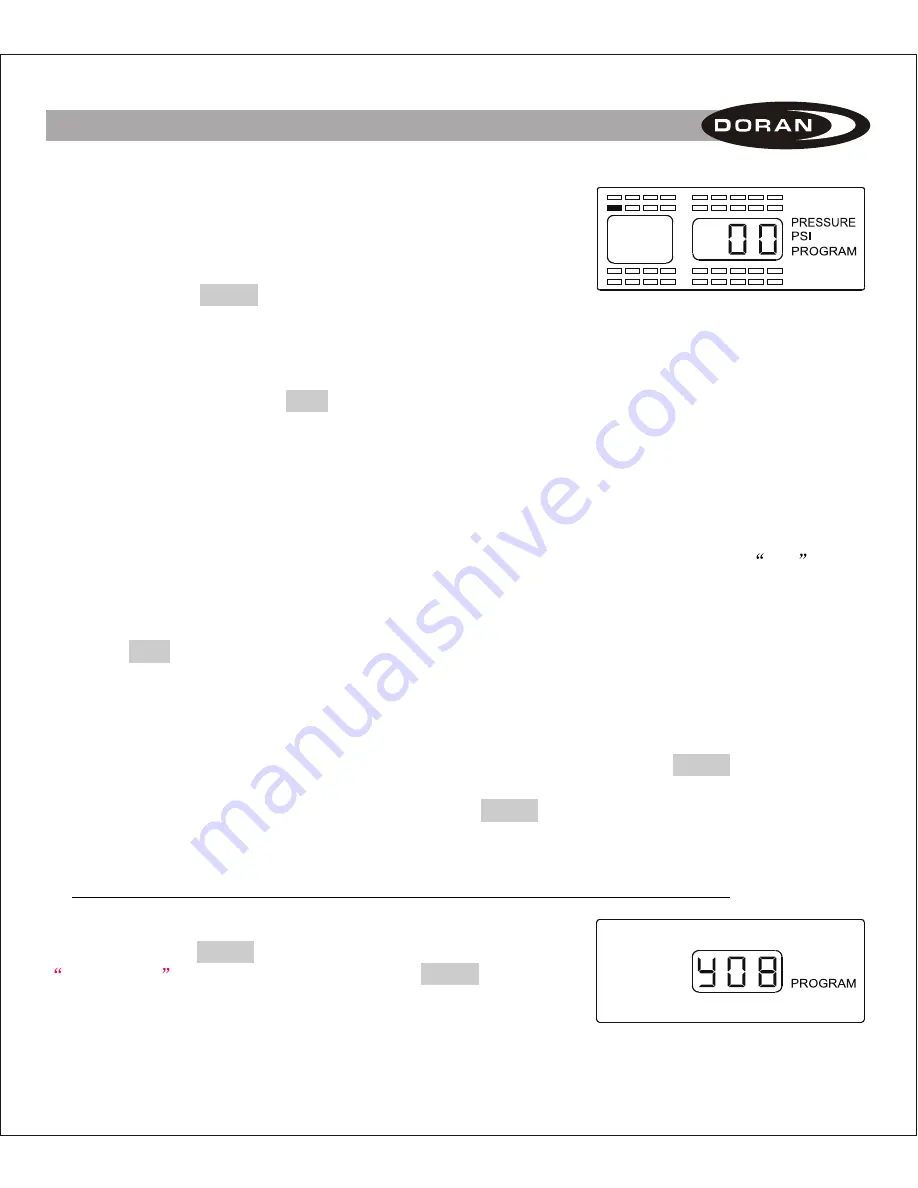
NOTE: To enter directly into this program mode you will 
need to press the 

 button for 5 seconds until the

is displayed.  Then press the 

 button 

again briefly 2 times to enter this mode (

see Figure 2- 10 for 

screen display

).

PROG

ROGRAM

PROG

P

Figure 2-10

II. SETUP AND INSTALLATION

Summary of Contents for 360RV

Page 1: ...The DORAN 360RV is designed solely to monitor tire pressure It is not designed to provide warning of a potential or actual tire blowout The National Highway and Traffic Safety Administration considers...

Page 2: ...tion F High Pressure Alarm Programming III Installing the Sensor on the Vehicle IV Alarm Modes 1 First Stage Alarm for 12 5 Low 2 Second Stage Alarm for 25 Low 3 High Pressure Alarm 4 Lost Sensor Alar...

Page 3: ...RF products signal interruption can occur and prevent a signal to reach the monitor When used properly the Doran 360RV will inform the driver of the tire pressures on the vehicle so the operator has...

Page 4: ...not any faults the monitor will display a green light and the display will show ON Alert Mode When the monitor has received a signal that is outside of the parameters of the Normal Operation an alert...

Page 5: ...rette power adapter will need to be removed from the power cord and then you will see that there are three wires in the harness we suggest that you leave a few inches of wire on so you can use the plu...

Page 6: ...attempted to install the system and the sensors have not been programmed into the monitor the system will need to be programmed per the following section PROG Used to enter the program modes Also use...

Page 7: ...nd then you can release the button When you have entered this mode the monitor will display all of the tire positions and the word PROGRAM will be displayed see Figure 2 1 As you will see by Figure 2...

Page 8: ...ay 6 The center dash of this digit will now blink see Figure 2 5 Use the up and down button to change this digit to the number needed for the second digit of the sensor When you have selected the corr...

Page 9: ...nd Time for Stored Alarm History Information just press the PROG button briefly 1 time The display should look like Figure 2 10 Anytime during this mode you can escape out to the next program mode by...

Page 10: ...he baseline pressure would be imputed as 095 3 Press the left or right arrow button to select the next digit Use the up and down arrow buttons to change that digit When you have entered the number tha...

Page 11: ...e The monitor will now display like Figure 2 12 2 To adjust the Month M you will need to press and hold the SET button until the center digit flashes The months will be displayed as 01 for January thr...

Page 12: ...will need to press and hold the SET button until the center digit flashes You will notice that the Month and Minute both use the M Pressing the up and down arrow buttons will adjust the value of this...

Page 13: ...e The monitor is also capable of displaying the air pressure in BAR and kPa see Figure 2 18 and 19 If you want the monitor to read in PSI then nothing needs to be done except to press the PROG button...

Page 14: ...e press and hold the PROG button for 5 seconds The monitor will display the available sensors to delete and the words PROGRAM and DELETE will be displayed on the screen see Figure 2 20 If a sensor doe...

Page 15: ...de The HIGH PRESSURE PROGRAM mode will allow you to set up your monitor to alarm if a pressure that is 25 higher than the baseline pressure is detected This feature can assist in the checking of eleva...

Page 16: ...a metal stem It does improve the life of the stem due to premature failure from drying out and cracking Inferior stems have been found in the market and can cause extensive damage The dill valve at ea...

Page 17: ...SORS ON THE VEHICLE 15 Figure 3 3 1 If the sensors have been programmed to the monitor you will now need to install the sensors onto the proper wheel positions on the vehicle The sensor should be tigh...

Page 18: ...ALARM MODES An alert indicates that you are operating your vehicle in a dangerous condition When the low pressure light illuminates STOP and check your tire s as soon as safely possible and inflate th...

Page 19: ...l only be displayed during the fast leak and will go out after 18 seconds when the air quits leaking from the tire We suggest that the tire be inspected immediately Figure 4 1 Figure 4 2 On a level 2...

Page 20: ...will go out The audible beeper will beep once per second and HIGH PRESSURE will be displayed on the monitor screen This can be caused by extreme heat generated into the tire When the High Pressure wa...

Page 21: ...e section that is not selected will drop from the screen see Figure 5 2 and 5 3 4 When your selection is made press both the front and rear arrow buttons for 5 seconds and this will lock your selectio...

Page 22: ...s is necessary It is unlikely that the typical RV enthusiast will require this feature Monitoring the faults and when they occur can be a useful tool for the over the road trucking industry To enter t...

Page 23: ...finished checking the alarm history the PROG and SET buttons can be pressed together for three seconds to return to the normal operation mode Figure 6 6 Figure 6 7 4 Backlight on for night operation T...

Page 24: ...le just a few feet can sometimes overcome this problem The sensor will need to be removed and re installed to activate the sensor for it to report quickly to the monitor If you are using an optional s...

Page 25: ...hen less than 5 lbs of air pressure are present When putting system back on power monitor first and then screw sensors onto their original wheel locations Pressure reading will display within a few mi...

Page 26: ...once per second until low pressure is corrected or a button is pressed to place Monitor in Quiet Mode 2 Air pressure has dropped to the second alert level 25 under your programmed pressures Alert will...

Page 27: ...rofessional ROTATING REPLACING TIRES When rotating or replacing tires mark wheel location of each sensor Remove sensors and store in bags or in an egg carton until work is done and then return the sen...

Page 28: ...mitation acts of God or exposure to abrasive or corrosive materials or pollutants or attributable to collision or other accidents involving motorcycles upon which the DORAN 360RV is installed LIMITATI...

Page 29: ...for any dispute in connection with the purchase or use of the product shall be the state and federal courts of general jurisdiction located in Hamilton County Ohio U S A SPECIAL NOTICE TO CONSUMERS I...

Page 30: ...INTERFERENCE AND 2 THIS DEVICE MUST ACCEPT ANY INTERFERENCE THATMAY CAUSE UNDESIRED OPERATION THE DORAN 360RV IS A DEVICE FOR DISPLAYING TIRE PRESSURES AS WITH ALL DEVICES THAT USE RF SIGNALS THE SIGN...

Reviews: