background image

7

Donaldson Company, Inc.

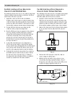
Fan With Inlet Spool Piece Mounted to 

Clean Air Outlet  Without Weld Nuts

The following instructions are for a fan with an integrated 

inlet spool piece being mounted on collectors that do 

NOT have weld-nuts on the clean air outlet.
1.  Apply the sealer, furnished in the installation 

hardware kit, around clean air outlet opening of the 

collector. Sealer should be applied in a Figure 8 type 

pattern around each bolt hole so that inlet is sealed 

from both the outside and the inside of the bolt hole.

2.  Remove the inlet spool from fan. Retain the hardware 

to  for use when fan is reattached to the spool in 

Step 5.

3.  Position the inlet spool piece onto the collector 

surface. Align mounting holes.

4.  Bolt the inlet spool piece to the collector clean 

air outlet by inserting supplied hardware. Reach  

through to secure the nuts on the inside of the clean 

air plenum. Apply supplied Loctite on nut. 

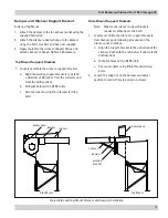
Fan With Inlet Spool Piece Mounted to 

Clean Air  Outlet With Weld  Nuts

The following instructions are for a fan with an integrated 

inlet spool piece being mounted on collectors that have 

weld-nuts on the clean air outlet.
1.  Apply the sealer, furnished in the installation 

hardware kit, around clean air outlet opening of the 

collector. Sealer should be applied in a Figure 8 type 

pattern around each bolt hole so that inlet is sealed 

from both the outside and the inside of the bolt hole.

2.  Position TBI fan and spool assembly onto the 

collector surface. Align mounting holes.

3.  Bolt the TBI fan and spool assembly to the collector 

clean air outlet by inserting hardware supplied 

through the inlet spool piece and into the weld nut 

in the clean air plenum. Be sure to position the 

discharge to be free of obstructions and locate so 

that the motor’s electrical box will be positioned for 

wiring convenience.

4.  Inspect the installation prior to starting the fan. 

Check for any loose items or debris that could be 

drawn into the fan or dislodged by the air discharged 

from the fan outlet. Check the interior of the fan as 

well. Turn the wheel by hand to check for binding.

5.  Complete the electrical connections in accordance 

with NEC code and state and local codes. “Bump” 

the starter to make sure the motor is rotating in 

the proper direction. (Standard TBIs are clockwise 

rotation as viewed from the motor endbell.)

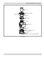
spool

apply loctite to 

threads and face 

of nut

cabinet (reference)

Steps 3-4

Step 2

Summary of Contents for TBI 10

Page 1: ...manual DO NOT operate or perform maintenance on this collector until you have read and understood the instruction and warnings contained within this manual Torit Backward Inclined Fan TBI 3 to 30 60...

Page 2: ...ipment This manual has been supplied to assist with the installation operation and maintenance for the collector purchased Please read the manual before installing operating or performing maintenance...

Page 3: ...ts 7 Fan With Inlet Spool Piece Mounted to Clean Air Outlet Without Weld Nuts 7 Motor Drain Hole Orientation Side Mount Fans 8 Fan with Inlet Spool Piece Mounted to Clean Air Outlet with Adapter 8 Fan...

Page 4: ...or materials remains the responsibility of the process owner operator Donaldson may provide referrals to consultants suppliers of equipment or services related to the detection and or mitigation of s...

Page 5: ...ector to be filtered Cleaned air exits the collector via the outlet of the TBI Fan Inspection on Arrival 1 Inspect equipment and parts on delivery 2 Report any damage to the delivery carrier 3 Request...

Page 6: ...odically Rotate the wheel by hand every two weeks to redistribute grease on motor bearing parts Installation Codes and Procedures Codes may regulate recirculating filtered air in your facility Consult...

Page 7: ...View the fan rotation through the back of the motor To reverse rotation three phase power supply switch any two leads on the output side of the motor starter Do not interchange a power lead with the...

Page 8: ...he motor manufacturer TBI fans are dynamically balanced and tested at operating speeds to check for conformance to vibration limits All fans must be adequately supported for smooth operation Safe oper...

Page 9: ...n TBI 3 through 30 6 Fan Installation motor lifting points lifting points fan wheel inlet cone fan housing sealant sealant spool not supplied on all fan assemblies dust collector clean air outlet refe...

Page 10: ...weld nuts on the clean air outlet 1 Apply the sealer furnished in the installation hardware kit around clean air outlet opening of the collector Sealer should be applied in a Figure 8 type pattern aro...

Page 11: ...erior of the fan as well Turn the wheel by hand to check for binding 4 Complete the electrical connections in accordance with NEC code and state and local codes Bump the starter to make sure the motor...

Page 12: ...inal position later in Step 6 3 Remove the motor wheel assembly from the fan housing Do not remove the wheel from the motor shaft 4 Position the fan housing onto the collector surface with the fan inl...

Page 13: ...the silencer pack drawings a Align the support bracket to the underside of the silencer flush with the cabinet wall and mark the drill locations b Drill pilot holes with a 0 339 in bit c Secure bracke...

Page 14: ...termined by the severity of the application and local conditions Strict adherence to an inspection schedule is essential When installing a new wheel or cone the proper wheel to drive side plate must b...

Page 15: ...00 hours In severe dirt and abrasive dust conditions grease every 2750 hours Under extreme conditions such as an environment with iron dust grease every 550 hours Wheel Balance Airstreams containing p...

Page 16: ...t adjusted properly Check airflow in duct Adjust damper control until proper airflow is achieved and the blower motor s amp draw is within the manufacturer s rated amps Electrical circuit overload Che...

Page 17: ...tion or installed backwards on shaft Proper fan rotation is clockwise from the top of the fan The fan can be viewed through the back of the motor Poor system design closed dampers air leaks or clogged...

Page 18: ...__________________________________________________________ Dust Properties Kst_______________Pmax______________MIE____________MEC_________________ Accessories__________________________________________...

Page 19: ...manufactured by a third party Third Party Product may constitute contain be contained in incorporated into attached to or packaged together with the goods Buyer agrees that a Third Party Products are...

Page 20: ...mportant Notice Many factors beyond the control of Donaldson can affect the use and performance of Donaldson products in a particular application including the conditions under which the product is us...

Reviews: