


Downflo Oval, DFO 2-4 and 3-6
36
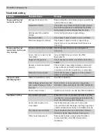
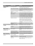
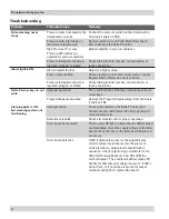
Problem
Probable Cause
Remedy
Insufficient airflow
continued
Lack of compressed air
See Rating and Specification Information for
compressed air supply requirements.
Pulse cleaning not energized
Use a voltmeter to check the solenoid valves in the
control panel. Check pneumatic lines for kinks or
obstructions.
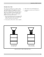
Dust storage area overfilled or
plugged
Clean out dust storage area. See Dust Disposal.
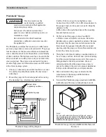
Pulse valves leaking
compressed air
Lock out all electrical power to the unit and bleed
the compressed air supply. Check for debris, valve
wear, pneumatic tubing fault, or diaphragm failure by
removing the diaphragm cover on the pulse valves.
Check for solenoid leaks or damage. If pulse valves
or solenoid valves and tubing are damaged, replace.
Solid-State timer failure
Using a voltmeter, check supply voltage to the timer
board. Check and replace the fuse on the timer
board if necessary. If the fuse is good and input
power is present but output voltage to the solenoid
is not, replace the timer board. See Solid-State Timer
Installation.
Solid-State timer out of
adjustment
See Solid-State Timer and Solid-State Timer Wiring
Diagram.
No display on the Delta P
Controller
No power to the controller
Use a voltmeter to check for supply voltage.
Fuse blown
Check the fuse in the control panel. See wiring
diagram inside the control panel. Replace if
necessary.
Display on Delta P
Controller does not read
zero when at rest
Out of calibration
Recalibrate as described in Delta P Maintenance
Manual.
With collector discharging
outside, differential pressure is
present from indoor to outdoor
Recalibrate with the pressure tubing attached as
described in the Delta P Maintenance Manual.
Delta P Controller ON,
but cleaning system does
not start
Pressure tubing disconnected,
ruptured, or plugged
Check tubing for kinks, breaks, contamination, or
loose connections.
Not wired to the timing board
correctly
Connect the pressure switch on the timer board to
Terminals 7 and 8 on TB3.
Faulty relay
Using a multimeter, test relay for proper closure.
Replace if necessary.
Summary of Contents for DFO 2-4
Page 1: ...2...
Page 3: ......
Page 5: ......
Page 12: ......
Page 14: ......
Page 15: ......
Page 17: ...Downflo Oval DFO 2 4 and 3 6 14 This Page Intentionally Left Blank...
Page 19: ......
Page 21: ...Downflo Oval DFO 2 4 and 3 6 18 This Page Intentionally Left Blank...
Page 22: ......
Page 23: ......
Page 24: ......
Page 30: ......
Page 37: ......
Page 41: ...Downflo Oval DFO 2 4 and 3 6 38 Service Notes Date Service Performed Notes...
Page 42: ...39 Donaldson Company Inc Service Notes Date Service Performed Notes...
Page 43: ......