


61
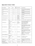
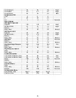
Appendix V Alarm Table
Alarm description
Reset
Delay
Alarm
relay
System Action
Corrective Action
Chilled Water Supply Sensor
Failure
Manual
Immediate
Yes
Shuts off Unit
Check sensor for shorts and opens and
compare temperature reading with digital
thermometer
Chilled Water Return Sensor
Failure
Manual
Immediate
Yes
Shuts off Unit
Check sensor for shorts and opens and
compare temperature reading with digital
thermometer
Sea Water Inlet Sensor
Failure
Manual
Immediate
Yes
Warning Signal
Check sensor for shorts and opens and
compare temperature reading with digital
thermometer
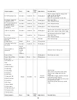
Chilled Water Supply High
Manual
10 sec
Yes
Turns off
compressor or
heat relay
Check for low water flow due to restrictions or
pump wear
Chilled Water Supply Low
Manual
10 sec
Yes
Turns off
compressor or
heat relay
Check for low water flow due to restrictions or
pump wear
Sea Water Inlet Low
Manual
10 sec
Yes
Warning Signal
Low temperature due to geographical climate
Chilled Water Flow
After 3
retries every
30 mins,
must be
reset
Manually
Immediate
Yes
Turns off
compressor or
heat relay
Check for proper loop water flow and make
sure strainers are not clogged.
Check for defective flow switch
Bleed air out of the loop water
Check loop water pump
High Discharge Pressure
After 3
retries every
30 mins,
must be
reset
Manually
Immediate
Yes
Shut off Unit
Check for proper refrigerant pressure with
gauge, if normal then check for defective
pressure switch.
Assure proper sea water and loop water flow
and make sure water strainers are not
clogged.
Ensure system is not overcharged.
Low Suction Pressure
After 3
retries every
30 mins,
must be
reset
Manually
60 sec
Yes
Shut off Unit
Check for proper refrigerant pressure with
gauge, if normal then check for defective
pressure switch.
Assure proper sea water and loop water flow
and make sure water strainers are not
clogged.
Ensure system is not undercharged.
Low Pressure Differential
Check EEV motor
Compressor Start Failure
After 5 times
in 60 mins
must be
reset
Manually
10 sec
Warning Signal
Check voltage to compressor.
Check Power inverter.
Condenser Out
Temperature Sensor Failure
Manual
Immediate
Warning Signal
Check sensor for shorts and opens and
compare temperature reading with digital
thermometer
High Discharge Gas
Temperature
Automatic
30 sec
Warning Signal
Check for proper refrigerant pressure with
gauge
EVD Evo Probes fault or
disconnected (S1,S2,S3,S4)
Automatic
Immediate
Yes
Off compressor
Check condition of the wiring and connections
Summary of Contents for VARC 48
Page 20: ...18 Appendix I Touchscreen Navigation MAIN PAGE Figure 15 CHILLER ENABLE Figure 16...
Page 21: ...19 CHILLER SETPOINTS Figure 17...
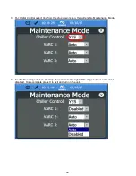
Page 22: ...20 Figure 18 CHILLER STAGE Figure 19...
Page 24: ...22 TRENDS Figure 21 Figure 22...
Page 25: ...23 ACTIVE ALARMS Figure 23 ALARM HISTORY Figure 24...
Page 26: ...24 ALARM HELP Figure 25 Figure 26...
Page 27: ...25 REMOTE SUPPORT Figure 27 REMOTE ENABLE Figure 28...
Page 28: ...26 REMOTE CONFIGURATION Figure 29...
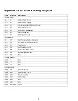
Page 41: ...39 Basic wiring diagram...
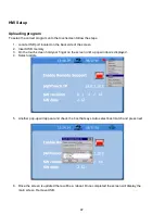
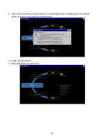
Page 55: ...53 7 Use Next or Back to scroll to Display Settings 8 Select Display Settings...
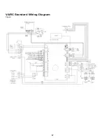
Page 69: ...67 VARC Standard Wiring Diagram Figure...
Page 70: ...68 NOTES...
Page 71: ...69 NOTES...


