


42
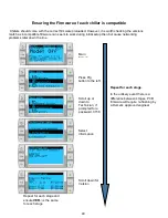
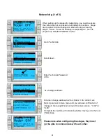
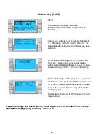
Networking (2 of 3)
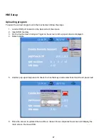
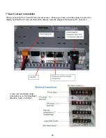
Chiller stage 2 needs to have a display address of
17, chiller stage 3 will be 18 and 4 will be 19. I/O
Board address should reflect the change you have
just made
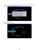
Press and hold Up, Down and Enter
simultaneously until screen changes, about 6
seconds
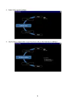
At this point screen may go blank, if it does, start
from step 1 again (above) and ensure display
address and I/O board address is correct for stage.
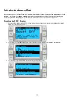
Press enter to go into the terminal config settings
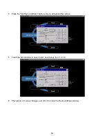
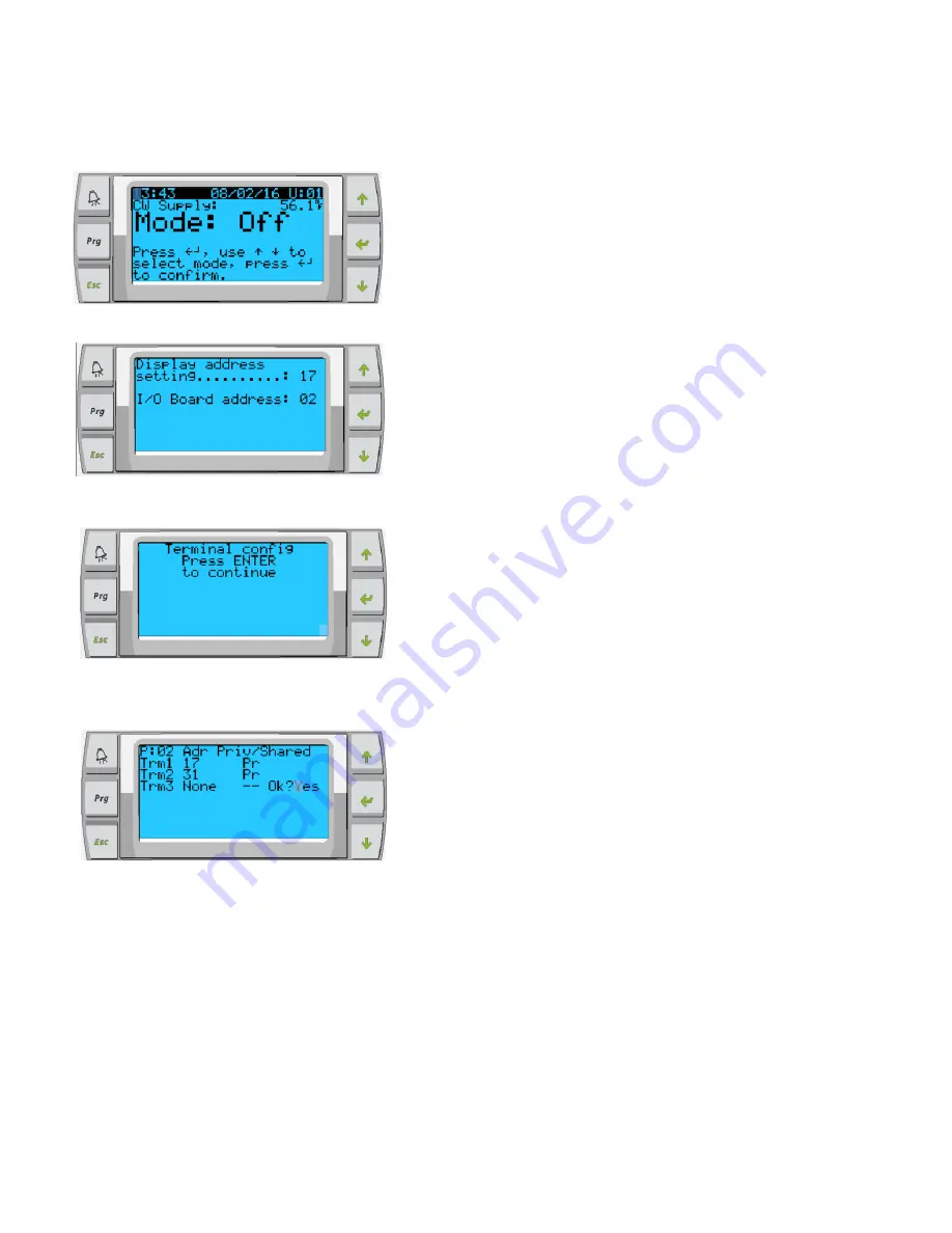
Trm1 = 17 for stage 2, 18 if stage 3 etc… and Pr
ID 32 & Sh - this will allow for PGD1 control if used.
ID 31 & Pr
– this will allow for touchscreen if used.
Only enable controls that are being utilized in the
working system.
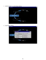
Press enter until you get to OK? Change to Yes to
save settings.
Power down stage and repeat process for all stages, once all complete. Turn on stage 1
and repeat this page (only) ensuring Trm1 = 16 Pr
Step 1
Summary of Contents for VARC 48
Page 20: ...18 Appendix I Touchscreen Navigation MAIN PAGE Figure 15 CHILLER ENABLE Figure 16...
Page 21: ...19 CHILLER SETPOINTS Figure 17...
Page 22: ...20 Figure 18 CHILLER STAGE Figure 19...
Page 24: ...22 TRENDS Figure 21 Figure 22...
Page 25: ...23 ACTIVE ALARMS Figure 23 ALARM HISTORY Figure 24...
Page 26: ...24 ALARM HELP Figure 25 Figure 26...
Page 27: ...25 REMOTE SUPPORT Figure 27 REMOTE ENABLE Figure 28...
Page 28: ...26 REMOTE CONFIGURATION Figure 29...
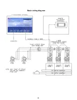
Page 41: ...39 Basic wiring diagram...
Page 55: ...53 7 Use Next or Back to scroll to Display Settings 8 Select Display Settings...
Page 69: ...67 VARC Standard Wiring Diagram Figure...
Page 70: ...68 NOTES...
Page 71: ...69 NOTES...


