


13
o
Date:
Change date here.
o
Hour:
Change time here.
o
Day:
Displayed
Next Screen:
o
DST:
Enabled (Default)
o
Description Follows:
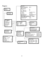
Menu D: Input/Output
View values or status of analog sensors, digital inputs or relay outputs.
o
A: Analog Inputs:
o
CW Return
o
Input B001:
Actual Value
o
Scroll for additional sensor values with down arrow button then ESC to exit.
o
B: Digital Inputs:
o
Flow Switch
o
DI 3 Status:
Actual State (Open or Closed)
o
Scroll Down for additional active digital inputs. This will change depending on what is enabled in the system
configuration.
o
C: Relay Outputs:
o
SW Pump
o
Relay 1 Status:
Actual State (ON or OFF)
o
Scroll Down for additional active relay outputs. This will change depending on what is enabled in the system
configuration.
o
D: Analog Outputs:
o
NOT USED
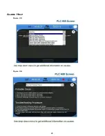
Menu E: Alarm History
Will capture the status of the following parameters at the time of the alarm. The most recent alarm will be shown. Use up arrow to
to view previous alarms.
o
Alarm will be displayed followed by:
o
Comp Speed:
Actual value
o
CW Return:
Actual value
o
CW Supply:
Actual value
o
Discharge Pres:
Actual value
o
Suct Pres:
Actual value
Menu F: Board Switch
This menu allows you to change to view additional boards and make changes to that particular board. This only applies to a
multi-stage configuration when units are networked together.
o
Unit Address:
1 (Default)
o
Switch to unit:
Desired board address
Menu G: Technician
Some subscreens will require a password. Please contact Dometic for service password.
Submenus:
Summary of Contents for VARC 48
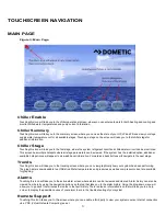
Page 20: ...18 Appendix I Touchscreen Navigation MAIN PAGE Figure 15 CHILLER ENABLE Figure 16...
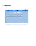
Page 21: ...19 CHILLER SETPOINTS Figure 17...
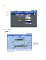
Page 22: ...20 Figure 18 CHILLER STAGE Figure 19...
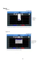
Page 24: ...22 TRENDS Figure 21 Figure 22...
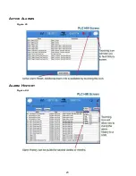
Page 25: ...23 ACTIVE ALARMS Figure 23 ALARM HISTORY Figure 24...
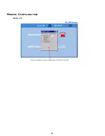
Page 26: ...24 ALARM HELP Figure 25 Figure 26...
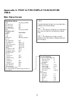
Page 27: ...25 REMOTE SUPPORT Figure 27 REMOTE ENABLE Figure 28...
Page 28: ...26 REMOTE CONFIGURATION Figure 29...
Page 41: ...39 Basic wiring diagram...
Page 55: ...53 7 Use Next or Back to scroll to Display Settings 8 Select Display Settings...
Page 69: ...67 VARC Standard Wiring Diagram Figure...
Page 70: ...68 NOTES...
Page 71: ...69 NOTES...


