10
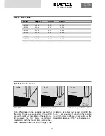
The refrigerator must be installed
draught-proof
in a recess (also refer to Section 6.2). The mea-
surements of the recess are stated in the table
below. Step
A
is only required for cabinets with a
step. Push the appliance far enough into the
recess until the front edge of the refrigerator
casing is aligned with the front of the recess.
Allow a gap of
2.32
"-
3.1
"
between the back wall
of the recess and the refrigeration unit. The floor
of the recess must be level, allowing the applian-
ce to be pushed easily into its correct position.
The floor must be substantial enough to bear the
weight of the appliance.
1.6
Installation recess
Ensure that the refrigerator is installed level in the recess.
Fig. E23
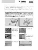
Installing the standard fume flue:
Fig. E22
1.
Connect T-piece (E) to adaptor (F) or flue
pipe (K) as required and affix with screw (G).
Ensure that heat baffle (H) is lodged in the cor-
rect position.
2.
Insert flue pipe with cover plate (C) through
the appropriate aperture in the upper frame (I)
and connect to T-piece (E). If necessary, shorten
flue pipe (C) to the required length.
3
. Insert
L100
ventilation grille (D) into mounting
frame (I) and fasten, using the locking handle on
the left of the grille.
4
. Put cap (B) on flue pipe (C).
5
. Insert extractor insert (A) into ventilation grille
(D).
The exhaust gas duct system must be made in
such a manner as to achieve a complete extrac-
tion of combustion products to the outside of
living space. The duct system must slope in an
upward direction in order to avoid a build-up of
condensate. The type of exhaust gas duct
shown in Fig. E22 allows the side installation of
the winter cover.
An installation other than described will
reduce the cooling capacity and jeopardise
the manufacturer's warranty/product liability.
1.5
Exhaust gas duct and installing the fume flue
CAUTION
A
Summary of Contents for RML 8551
Page 18: ...18 Fig E35 2 0 Tables and wiring diagrams 2 1 Wiring diagrams 2 1 1 Wiring diagram RM 8xx0...
Page 19: ...19 Fig E36 2 1 2 Wiring diagram RM 8xx1 THE SIGN OF COMFORT...
Page 20: ...20 Fig E37 2 1 3 Wiring diagram RM 8xx5...
Page 21: ...21 Fig E38 2 1 4 Wiring diagram RM 8xx5 with electrical doorlock optional THE SIGN OF COMFORT...
Page 23: ...23 THE SIGN OF COMFORT...
Page 24: ......
Page 47: ...23 THE SIGN OF COMFORT...
Page 48: ......

