7
OPTIONS
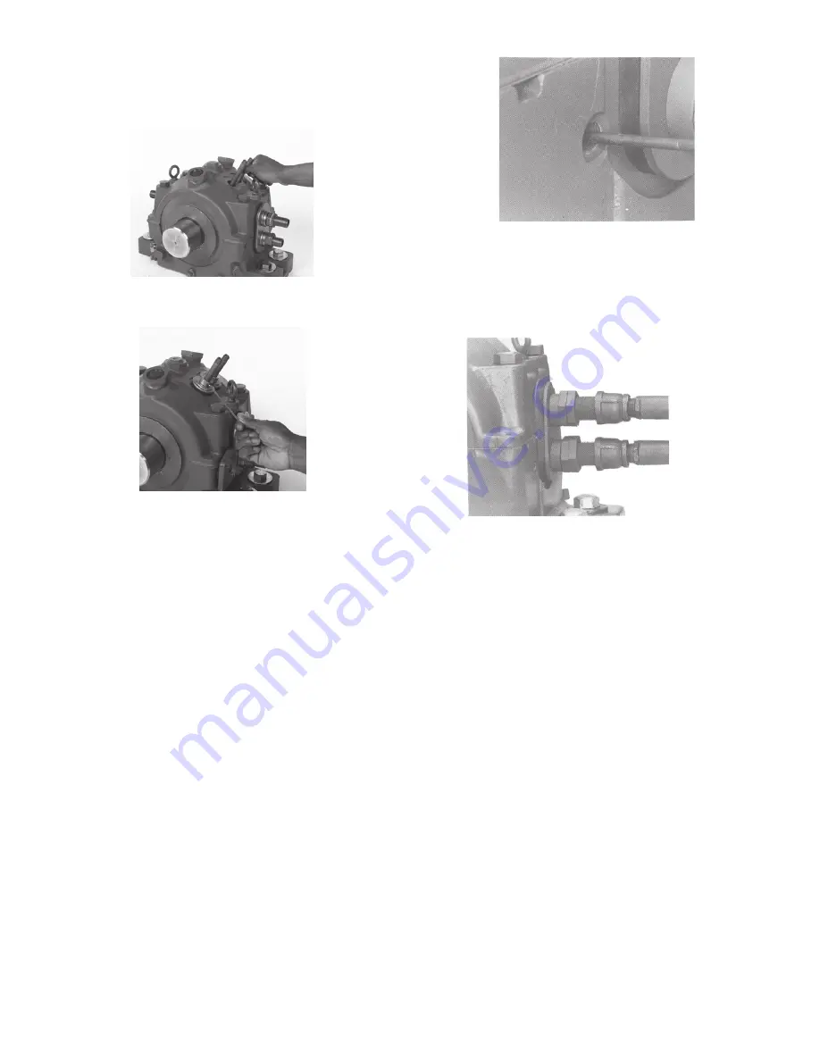
When pillow block is arranged for circulating oil, insert the two
small pipe nipples thru the holes in the housing cap and screw
them tightly into the liner.
Install grommet, grommet plate and collar over each inlet pipe.
Press down on collar and tighten collar set screw.
NOTE: ALL plumbing (oil and water) should be cleaned and
flushed before being connected to the pillow block. These
systems should be tested before the bearing is put into
operation.
Connect circulating oil supply lines so that each inlet receives an
equal amount of oil. A flow control valve and oil flow indicator
are recommended in the inlet line. Oil flow must be adjusted to
the rate recommended by the equipment manufacturer. Connect
the drain lines. The drain piping should be vented and must be
of adequate size to remove the oil at the specified flow rate. The
housing drain must be directed straight down into a return drain
sloping away at a 15º or greater angle. The oiling system should
have a means of filtering the oil to remove any contaminating
particles. A 25 micron filter or better is recommended.
It is strongly recommended to use thermocouples or RTDs
to monitor the bearing bore temperature during operation.
Probe diameters should be a maximum of 1/4”. There are two
designated thermocouple/RTD holes machined in the housing
base next to the water pipe grommets. These two holes should
align with the two thermocouple/RTD holes drilled into the liner.
Install two RTDs/thermocouples in each bearing. Make sure the
probe tips contact the end of the drilled holes in the liner. Use
sealant on all threaded connections.
Check construction drawings to determine if coolant (water or air)
is to be supplied to the bearings. Do not connect coolant pipes
and bearing unless construction drawings and/or equipment
instructions call for this. If no connection is required, pipes can
be left open.
NOTE: ALL plumbing (oil and water) should be cleaned and
flushed before being connected to the pillow block These
systems should be tested before the bearing is put into
operation.
If coolant pipes are to be connected, make sure that all pipe
lengths are correct and unions are well aligned. Careless
fitting will result in serious preloading of the bearing. Lengths
of flexible hose between the pillow block and rigid piping are
recommended to avoid preloading of the bearing. A regulating
valve should be placed ahead of the inlet and a sight drain at
the outlet for liquid coolants. The recommended method of pipe
connection for liquid coolants is to connect the inlet to the top
pipe and the outlet to the bottom pipe on the same side of the
bearing. A return is then used to connect the two pipes on the
other side of the bearing. Adjust coolant flow to rate specified
on construction drawing or to suit conditions. Anti-freeze type
additives may be used in cold operating environments, otherwise
purge all coolant from liner by blowing out with compressed air
or steam anytime coolant is subject to freezing. Bearing rating is
generally based on a maximum water inlet temperature of 90ºF.
The interior pressure of the liner should never exceed 120 psi.
For deviations see construction drawings or contact equipment
manufacturer.


