CONTENTS
1. WARNING SYMBOLS ...........................................................................................................................................12
2. PURPOSE ...................................................................................................................................................................12
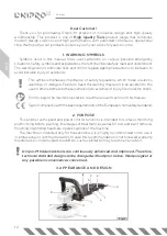
3. APPEARANCE AND DESIGN .........................................................................................................................12
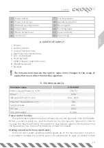
4. SCOPE OF SUPPLY ..............................................................................................................................................13
5. TECHNICAL DATA .................................................................................................................................................13
6. SAFETY MEASURES .............................................................................................................................................14
7. MAKEREADY .............................................................................................................................................................16
8. SWITCHING ON FOR THE FIRST TIME ......................................................................................................17
9. RECOMMENDATIONS FOR USE ..................................................................................................................17
10. STORAGE..................................................................................................................................................................18
11. DISPOSAL ..................................................................................................................................................................18
Summary of Contents for PM-160SP
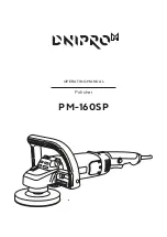
Page 1: ...MANUAL POLISHER PM 160SP UA PM 160SP RU PM 160SP...
Page 2: ......
Page 3: ...PM 160SP 2 OPERATION MANUAL Polisher 12 22...
Page 4: ...PM 160SP...
Page 5: ...1 2 2 2 3 3 4 3 5 4 6 4 7 7 8 8 9 8 10 9 11 9...
Page 6: ...2 Dnipro M High Quality Tools 1 2 Dnipro M...
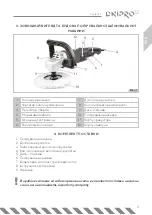
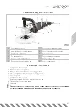
Page 7: ...PM 160SP 3 3 1 7 2 8 3 9 4 10 5 11 6 12 4 1 2 3 4 5 6 7 8 9 1 3 4 2 5 6 12 7 11 10 9 8 1...
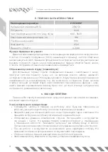
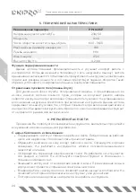
Page 8: ...4 5 PM 160SP 230 50 1600 600 3600 180 M14 IP20 4 2 4 4 6...
Page 9: ...PM 160SP 5 Dnipro M Dnipro M Dnipro M...
Page 10: ...6 1 2 3 4 5...
Page 11: ...PM 160SP 7 7 30 3 1 2 1 2 2 3 1 2 3...
Page 12: ...8 4 1 3 4 2 3 4 8 1 2 5 5 35 80 3 4 5 3 6 7 9 1 2 10 3 5 35 30 20 4...
Page 13: ...PM 160SP 9 60 C 50 30 60 5 600 3600 6 5 MIN MAX 15 3 1 1 1 2 1 10 11 4 5...
Page 14: ...PM 160SP OPERATING MANUAL Polisher...
Page 23: ...PM 160SP 19 ENG NOTES...
Page 24: ...PM 160SP...
Page 25: ...1 22 2 22 3 23 4 23 5 24 6 24 7 27 8 28 9 29 10 30 11 30...
Page 26: ...22 Dnipro M High Quality Tools 1 2 Dnipro M...
Page 27: ...PM 160SP 23 3 1 7 2 8 3 9 4 10 5 11 6 12 4 1 2 3 4 5 6 7 8 9 1 3 4 2 5 6 12 7 11 10 9 8 1...
Page 28: ...24 5 PM 160SP 230 50 1600 600 3600 180 M14 IP20 4 2 4 4 6...
Page 29: ...PM 160SP 25 Dnipro M...
Page 30: ...26 Dnipro M Dnipro M...
Page 31: ...PM 160SP 27 7 30 3 1 2 1 2 2 3...
Page 32: ...28 4 1 3 4 2 3 4 8 1 2 5 5 35 80 3 4 5 3 6 7 1 2 3...
Page 33: ...PM 160SP 29 9 1 2 10 3 5 35 30 20 4 60 50 30 60 5 600 3600 6 5 4 5...
Page 34: ...30 MIN MAX 15 3 1 1 2 1 10 11...
Page 35: ......
Page 36: ......

