


SuperSigma2 AM PMS
–
V1.5.6 17-1-2020
Page 13 (97)
©2019 DMC GmbH Herten Germany
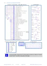
Pin 11
Analogue AD2 -- Footbrake pot
This pin is used only in traction application.
This is an analogue input that will accept a 3-wire 5k
Ω
potentiometer or a 0V to 5V voltage signal.
The active range of the footbrake input is defined
by the programmable parameters “
(0%) and “
(100%).
If a Footbrake switch is used on the brake pedal instead of an analogue device, the switch should connect this input
to the voltage corresponding to the value of parameter,
(100%) in order
to effect full braking.
•
The brake pedal input overrides the accelerator pedal input.
•
This analog input is deactivated if
”” is selected to 3 (Speed
Limit and Footbrake Switch). To activate a footbrake operation a foot brake switch must be
connected to the
Pin 6 Speed Limit 2 / Inch Reverse -- Pump Switch 6 (Power Steer Input)
.
•
If vehicle is rolling downhill (forward or backward), or in general motor spinning, controller
not pulsing and footbrake demanded, controller will start pulsing and braking according to
control Mode selection (see
Mode “Spd/Torq””). Controller keeps braking
the motor until footbrake pressed and speed different from zero. The end of braking type
and possible hill holding depends on setting (see
Pin 12
Analogue AD3 -- Steer pot
This pin is used only in traction applications.
The function is activated by means of parameter “
”” in the Controller Set
-
up menu.
It is activated both if set to 1 (Dual Motor Left) or 2 (Dual Motor Right) or 3 (Single Motor with steer pot. Speed
limit Right). The input can be connected to a 3-
wire 5kΩ pote
ntiometer that measures the steering angle of the
vehicle.
The active range of the input, when used by a steering potentiometer, is defined by the following parameters:
•
Steer pot minimum ”StrMin”” defines the voltage corresponding to the minimum steering angle (full
left hand lock)
•
Steer pot middle point ”StrMid”” corresponds to a 0° steering angle, i.e. the vehicle no steering
•
Steer pot maximum ”StrMax””. defines the voltage corresponding to the minimum steering angle
(full right hand lock)
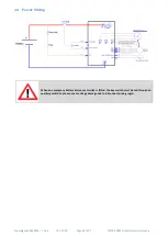
Pin 13
Key i/p
This input has to be connected to the switched side of the key switch. The other side of the key switch has to be
connected to the battery positive supply.
A 10 A fuse has to be connected between the battery positive supply and the key switch. The position of the fuse
should be as close as possible to the tap-off point for the key switch supply.
Pin 14
Contactor supply o/p
This output is the positive supply to the vehicle’s contactors
(line contactor, electro mechanical brake, power
steer). The volt
age level of this supply corresponds to the vehicle’s battery voltage. The maximum s
upply current
from this pin is 9A.
Pin 15
Contactor 1 o/p (Line)
This has to be connected to the negative side of the Line Contactor coil. The controller is driving this output. The
maximum rating for this connection is 3A and it is fully protected for use with inductive loads.


