


GENERAL OPERATION AND MAINTENANCE
WARNING:
The fiberglass handles end neoprene grips are NOT designed to protect the operator
In �
1
HOT" llne work I
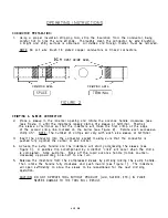
COLD WEATHER N DTE:
This tool and tool kit is supplied with Drydene Paradene 32AW hydraulic oil. For
operation below 20"F (-TC), refill reservoir with Drydene 22AW hydraulic oil. In cold
weather and non-use, 0-Ring seal sticking may cause non-pumping. rotate the
advance handle clockwise to advance the indenters and free any sticking 0-Rings.
STORAGE:
When tool is to be stored for any extended period of time, lhe tool should be
pumped up approximately every three (3) weeks to keep the 0-Rings and seals lubricated.
The tool should also be stored with the indenters in the fully open position.
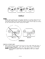
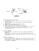
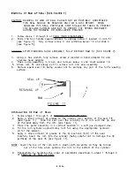
CAUTION: CRIMPING SMALL DIAMETERS SPLICES AND TERMINALS:
Extra care should be taken when positioning and crimping small diameter splices and
terminals. These items can become lodged between the tool head and the indenter
system (see Figure 4 ).
GENERAL MAINTENANCE:
The HC134 is a hydraulic crimp tool which requires well trained, experienced personnel
having a clean work area equipped with adequate tools for major repairs, adjustments
or maintenance.
PREVENTATIVE MAINTENANCE TOOL REQUIREMENTS
1. Hydraulic oil: Drydene Oil Co. Paradene hydraulic oil 32AW or 22AW depending upon
ambient temperature (see Cold Weather Note). DO NOT USE BRAKE FLUID!
2. DMC part number HP1036-RK Repair Kit.
3. An environmentally approved degreasing solvent.
4. Bench type vise having a 4" minimum opening and soft jaws.
5. Hex wrench set.
6. Pin punch set.
7. 1
o"
standard (flat blade) screwdriver.
El. 9/16·,
3/a"
and 5/8• open-end wrenches.
9. Lightweight hammer.
1 0. Oil catch pan.
11. DMC part number HPG1 Pressure Gauge.
12. Truarc® series 5133-25 E-Ring applicator.
DANIELS MANUFACTURING CORP. OFFERS A COMPLETE REFURBISHING AND
REC.ALIBR.ATION SERVICE.
CONTACT CUSTOMER SERVICE.
DMC ALSO SPECIALL ENGINEERS AND MANUFACTURES COMPLETE TOOL KITS TO SATISFY
SATISFY INDMDUAL CUSTOMER REQUIREMENTS, SUCH AS TOTAL SUPPORT, GENERAL
SHOP MAINTENANCE OR PRODUCTION, ON BOARD SHIP AND VEHICLE SERVICE, ETC.
PHONE (407) 855-6161
FAX (407) 855-68B4
E-MAIL: [email protected]
2. DF 28
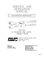
Summary of Contents for HC134
Page 26: ...PORT ON SEE NOTE p SIDE E 1 6...