


1 0. Push retaining ring 1 7 down firmly with a s u ita ble pin pu nch BY HAN D O NLY
u ntil it bottoms out on the shou lder.
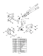
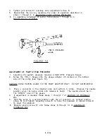
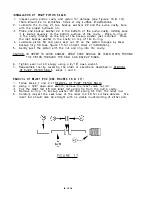
RE MOVAL OF BYPASS VALVE BALL:
1 . Fol low steps 1 th rough 4 of S ERVI CE OF INLET AN D OUTLET BALL VALVES
(see Fig ure 1 4) .
2 . Remove retaining ring 1 7, s pring 33 a n d ball 25.
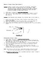
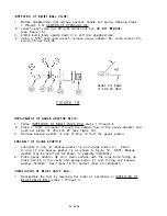
IN STALLATION
or
BYPASS VALVE BALL:
1 . Assemble the bypass valve by reversing steps 1 a nd 2 of REMOVAL OF BYPASS
VALVE BALL (see Figu re 1 3).
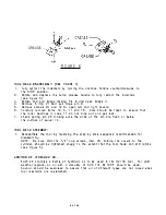
NOTE REGARDI NG TH E BODY PORT: This part is placed in the body d u ring the
m a n ufacturing p rocess a nd serves no purpose. Ba l l 24 is held to its seat by
screw 5 ( see Figu re 1 2) .
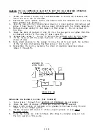
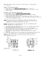
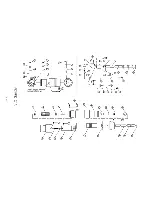
RE MOVAL O F PUM P PISTON SEALS (SEE FIGU RES 1 5 & 1 6):
1 . Before disassemb ly, first remove advance handle coil spring fol lowing ste ps 1
through 5 of ADDITI ON OF HYDRAU LIC OIL.
2. To rem ove p u m p handl e from pu mp body, re move the two retaining ri n gs 1 1
a nd pul l ha nd le pin 54. Grasp hand le grip and slig htly lift a n d pu l l the ha nd le
rea rwa rd.
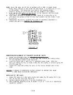
3. Hold pu m p body in a soft jaw equipped vise in an upwa rd position . Using a
9/ 1 6' open-end wrench , rem ove th e piston sea l nut 43 a n d gently pul l piston 50
from the p u mp body.
4. Remove the piston sea l n ut 43 a nd lift out the steel backu p ring 59, two
backup washers 22 and a -ri n g 2 1 .
NOTE: A s mal l hook formed from wire is handy fo r this purpose .
� � �CV�
�p �o��,
�
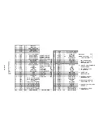
FIG URE 1 5
1 6 OF 2S
Summary of Contents for HC134
Page 26: ...PORT ON SEE NOTE p SIDE E 1 6...