
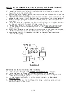
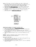


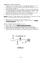


I NS P ECTI ON OF RELIEF BALL VALVE:
1. Before disassemble, first remove advance handle coil spring following steps
1 through 5 of ADDITION OF HYDRAULIC OIL.
2. Loosen relief valve nut 42 until almost out but DO NOT R[ MOVE !
(see Figure 16).
3. Clamp pum p body upside down in a soft jaw eq uipped vise.
4. Using a 5/EI" open-end wrench, remove gauge adaptor 45, crush washe r 23,
spring 35 an d ball 26.
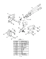
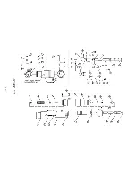
d "JJ !�u4
FIG URE 1 9
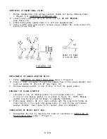
REPLAC[MENT OF GAUGE ADAPTOR SEALS:
):5.
l i Z i l
j
SCARF CUT ITEMS
1 4 AND 20 ONLY
1 . Follow INSP ECTION OF RELIEF VALVE BALL steps 1 through 4.
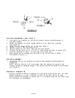
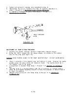
2. Place a 3/32" pin punch throug h the outside hole of the gauge adaptor and
push out piston 41 and ball 24 (see Figure 19).
3. Remove backup washer 14 and 0-Ring 12 from the gauge piston.
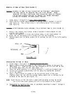
ASSEMBLY OF GAUG[ ADAPTOR :
1. Lubricate 0-ring 12, backup washer 14 and gauge pis ton 41. Install
0-ring 12 and backup washer 14 as shown in Figure 1 9. NOTE: Backup
washer may be scarf cut as shown to expedite installation.
2. Place gauge adaptor 46 on a clean surface with the large bore facing up.
Place ball 24 in the cavity and gauge piston 41 with 0-ring and backup
washer installed. See Fig ure 1 9 for correct order of installation.
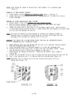
INSTALLATION OF RELIEF VALVE BALL:
1. Reassem ble the tool by reversing the order of operations in INSPECTION OF
RELIEF VALVE BALL, steps 1 through 4.
20 OF 2S
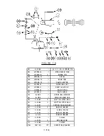
Summary of Contents for HC134
Page 26: ...PORT ON SEE NOTE p SIDE E 1 6...