background image

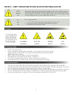
3.1 To Setup or Install Safely

!

3.2 Un-Packaging

3.3 Selecting a Location

3.4 Installation

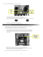
•     Connect water feed as indicated
•     Diversitech recommends that the overflow drain be connected to a suitable and approved collection/drainage.   
       The overflow drain is provided in case the water monitoring system fails.

6

SECTION 3 - SETUP / INSTALLATION

1.   Immediately upon receiving the unit, carefully examine the carton for damage during transit. 
2.   Remove packing material.
3.   Avoid tipping or inverting during handling.
4.   The item serial number, model, and electrical ratings are listed on the nameplate.  Record this information in the  
      Maintenance Record provided in 

APPENDIX 2: Maintenance Record

, or your own preventative maintenance system.


Drain

1 ½” NPT

Water Inlet

½” NPT

•     Choose a location where the unit will be used, near the operator.

•     Choose a location sufficiently close to a grounded power source.

•  Do not place unit near flammables or combustible surface.
•  Refer to SECTION 2: Specifications, to know the electrical requirements of the unit you are installing and ensure 
         adequate input power that is properly sized, rated, and protected. 
•  This unit must be grounded for safe operation.

Summary of Contents for TYPHOON WX Series

Page 1: ...t www diversitech ca 1200 55th Avenue Montreal Quebec H8T 3J8 Tel 1 800 361 3733 Fax 1 514 631 9480 info diversitech ca READ AND SAVE THESE INSTRUCTIONS WX 1200 WX 5000 WX 3000 WX 6500 Operation Maint...

Page 2: ...ERATION 9 4 1 To Operate Safely 9 4 2 Controls 9 4 3 Principles of Operation 10 Control System Explained 10 Water Level Monotoring 10 Alarms 11 Level Set Point 11 SECTION 5 MAINTENANCE TROUBLESHOOTING...

Page 3: ...that extracts fumes collects dusts and exhausts filtered air either indoors or outdoors Before use inspect the unit for damage and verify it is working properly Only qualified persons should install o...

Page 4: ...o 3000 5000 80 10 0 3P 60Hz 28 0 14 0 11 0 78 WX 6500 auto 4000 6500 80 15 0 3P 60Hz 34 0 16 9 14 0 80 1 For 1200 Airflow 2 external static pressure 2 For WX 3000 WX 5000 WX 6500 Airflow 2 5 external...

Page 5: ...PT WX 5000 16 61 117 57 1 2 NPT 1 NPT WX 6500 16 67 129 67 1 2 NPT 1 NPT 1 Water Level is marked on each unit Collector Model Table Model Optimal Connection a Footprint Water Water Level in Length b H...

Page 6: ...rting during handling 4 The item serial number model and electrical ratings are listed on the nameplate Record this information in the Maintenance Record provided in APPENDIX 2 Maintenance Record or y...

Page 7: ...cabinet Once reinstalled the electrical connection to the main control box must be made as per the provided wiring diagram The scrubber is designed to accommodate an auxiliary vent fan that operates w...

Page 8: ...to use in your application turn the unit ON and perform a function test To do so 1 Turn switch to ON position for a few seconds to check that the motor rotation is correct by looking down the back of...

Page 9: ...chanical moving parts including motor gears and other pinch points Do not use product without first confirming if a Spark Arrestor is required and installed for the type of dust or fumes you are extra...

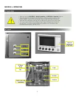
Page 10: ...h HEPA option 6 Interface for auxiliary vent fan 7 Current sensing alarm for auxiliary vent fan 8 Master Slave input for scrubber to run when dust producing equipment is on may require additional hard...

Page 11: ...m will remain until the situation is corrected Level Set Point Initial Set Point Adjustment if the PLC has been factory reset At the initial star up the set point will be at 0 To set the running water...

Page 12: ...this product Disconnect power before performing any maintenance on unit including filter inspection The input power to this unit is high voltage and touching any live electrical parts can cause fatal...

Page 13: ...Inspect the mist eliminator filters inside the unit for holes or dust accumulation replace the media if torn or dirty All debris must be stored in a ventilated metal drum to prevent hydrogen gas buil...

Page 14: ...vel Check input water and probes Fill to indicated level if necessary CORRECT Air Flow Restricted Air Flow Restricted Check clean pre filters and ducts between table and scrubber Check clean scrubber...

Page 15: ...ance on unit including filter inspection The input power to this unit is high voltage and touching any live electrical parts can cause fatal shocks or severe burns Do not touch live electrical parts A...

Page 16: ...the bicolor LED D rapidly flashes green 5 Releases the button The bicolor LED continues to flash green 6 Within 30s insert an object into position 1 then push and release the setup button The bicolor...

Page 17: ...m will be activated HEPA Installation HEPA installations follow NFPA guidelines thus temperature sensors are installed on the exhaust side of the HEPA filter These sensors are set at approximately 450...

Page 18: ...pied or otherwise reproduced as needed for management of maintenance records MANUFACTURER DIVERSITECH INC MODEL N WET COLLECTOR SERIAL N SERVICE LOCATION CONTROL N Date Description of Service Serviced...

Page 19: ...19 NOTES...

Page 20: ...se or use above rated capacities FREIGHT CLAIMS Shipments must be inspected upon arrival All Diversitech units are sold ex plant Therefore it is the receiver s responsibility to file any freight claim...

Reviews: