7/14
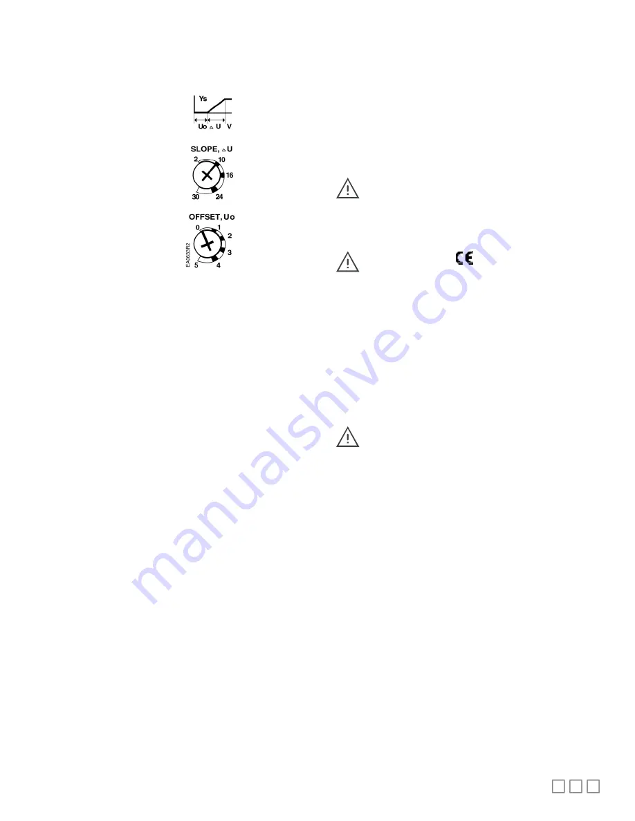
Slope (span) and Offset Adjustment
For DA-044N024PAXXP and DA-044N024PA2XP only
Factory setting:
Slope (span)
U
10
Offset Uo = 0
Use
a
flat-blade
screwdriver
to
make
adjustments. The long
arm of the
†
points to the
setting.
Figure 23.
Wiring
All wiring must conform to NEC and local codes and regulations.
Use earth ground isolating step-down Class 2 transformers. Do not use
autotransformers.
The sum of the VA ratings of all actuators and all other components
powered by one transformer must not exceed the rating of the
transformer.
Determine the supply transformer rating by summing total VA of all
actuators used. It is recommended that one transformer power no
more than 10 actuators.
All six outputs of the dual auxiliary switch (A and B) must
only be connected to:
-
Class 2 voltage (UL/CSA).
-
Separated Extra-Low Voltage (SELV) or Protective
Extra Low Voltage (PELV) (according to HD384 4 41)
for installations requiring conformance.
Installations requiring
Conformance
-
All wiring for CE rated actuators must only be
separated extra low voltage (SELV) or protective extra
low voltage (PELV) per HD384-4-41.
-
Use safety-isolating transformers (Class III transformer)
per EN 61558. They must be rated for 100% duty cycle.
-
Overcurrent protection for supply lines is maximum
10A.
Wiring Diagrams
Counterclockwise Damper Rotation of DA-044N024Fxxxx
If the damper blades turn counterclockwise to open (CCW), reverse the
6 (violet) and 7 (orange) wires at the controller.
(For DA-044N floating control actuator series only) To
prolong actuator life, use a controller and/or software that
provide a time-out function. This function removes the
actuator drive signal after the signal has been on for a
predefined time.


