background image

User manual in Original

Doc. ref: 500A_GTS-E65_am_en_210608
DISPERATOR AB


Tel: 08-724 0160   


E-mail: [email protected]

Mälarvägen 9, 141 71 Segeltorp   


Web page: www.disperator.se

20 / 48

6.   Installation Description for the Machine

6.1.1.   Deployment of the Machine

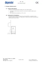
Unless otherwise requested in your order, the machine comes with its legs on a pallet. To 

minimize the risk of injury, at least two persons must be present when the machine is deployed. 

The machine has a net weight as per section 3.2 above, page 14, so the lifting equipment (e.g. 

forklift and pallet jack) to be used 

must be checked to withstand this weight.

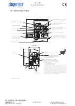
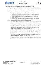
Lift the machine from the pallet at the socket positions in the cabinet bottom plate shown in the 

“Front view” in section 3.2, page 11 in this manual. Then move the machine to the designated 

place of installation.


Before the machine is set down on the floor, adjust the four legs so that the desired machine 

height is obtained. After the machine has been placed on the floor, check with a spirit level that it 

is horizontal, and adjust the legs if necessary.

6.1.2.   Fixation of the Machine

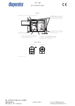
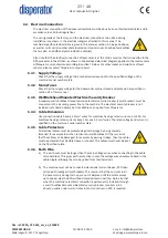
The machine must be fixed to the wall/bulkhead or floor/floor plate. When stopping quickly 

(e.g. if cutlery mistakenly jams the grinding unit) the torque of the disposer motor will cause 

the machine to turn. This can give undesirable forces on the pump’s connection to the drain 

pipe that goes to the tank (see paragraph 6.3 below), which can cause leakage. To prevent this, 

two adjustable brackets are included in the delivery for fixing the machine against a long wall or 

alternatively using 1pc against long wall and 1pc against corner wall. See section 3.2 (page 12, 

“Top view”) and section 5.2 above.

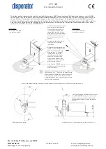
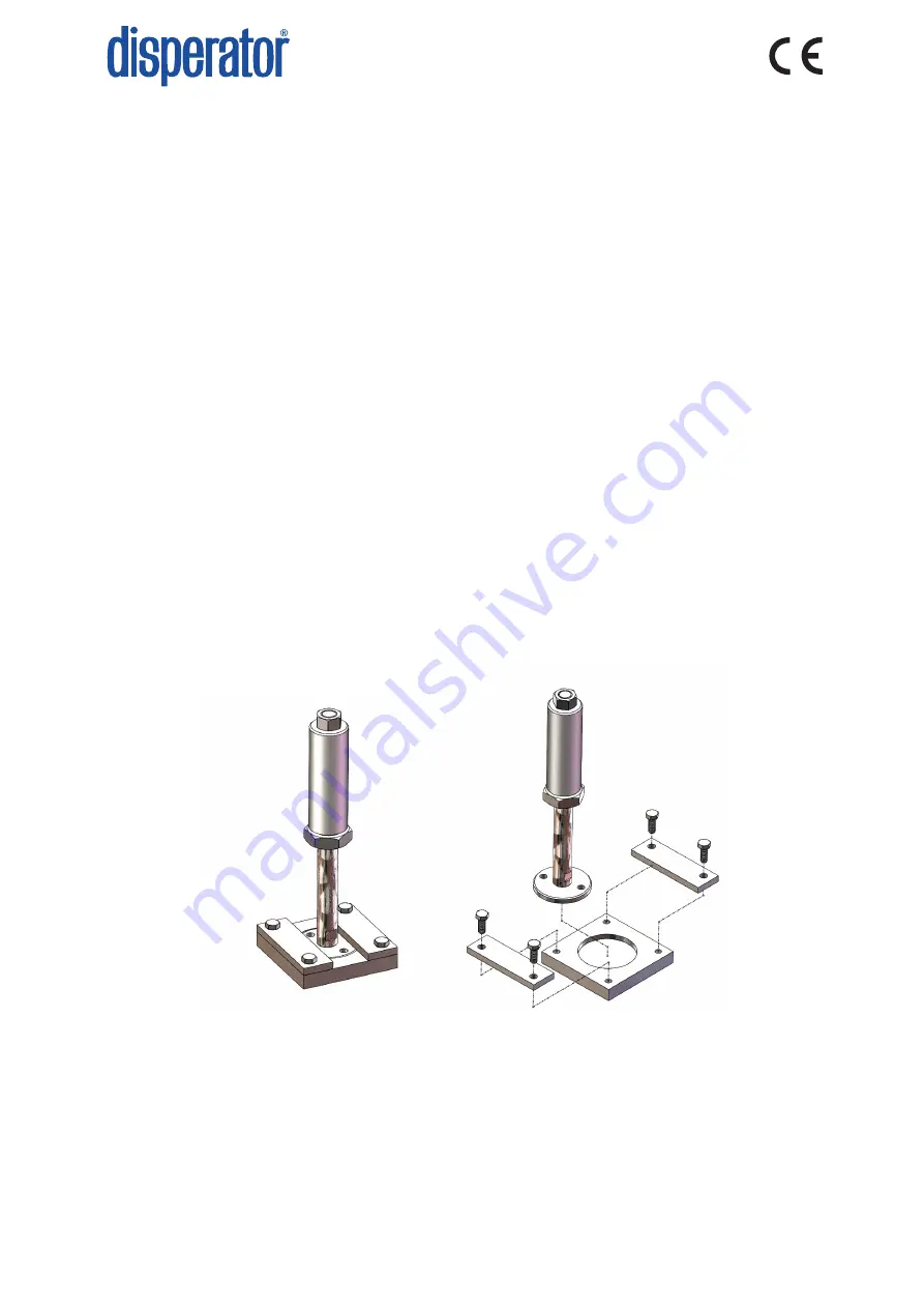
For marine installation the machine is instead fixed by means of e.g. plates which are welded to 

the floor plate, whereupon the machine legs are placed and screwed onto these plates as shown 

below.

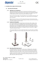
6.1.3.   Mounting of the Splash Guard

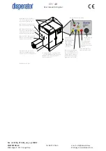
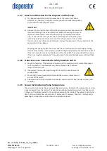
The delivered splash guard (see section 5.2 above) to be mounted against the outer edge of 

the cabinet top plate in such a way that one side of the cover is placed on back of the cabinet. 

Depending on the wishes of the kitchen, one or both short sides of the machine may also be 

equipped with splash guard. See section 3.2 above, page 13. Fix the delivered splash guard by 

screwing into the ready made holes in the outer edge of the cabinet top plate. After the splash 

guard has been fixed by screwing into these holes, seal off the gap between the top plate and 

splash guard with rubber sealant (silicone).

6.1.   Assembly of the Machine

Summary of Contents for 500A-GTS-E65 EXCELLENT SERIES

Page 1: ...RIES Product Description Installation Safety Operation Service USER MANUAL User manual in Original Doc ref 500A_GTS E65_am_en_210608 DISPERATOR AB Tel 08 724 0160 E mail info disperator se M larv gen...

Page 2: ......

Page 3: ...User manual in Original Doc ref 500A_GTS E65_am_en_210608 DISPERATOR AB Tel 08 724 0160 E mail info disperator se M larv gen 9 141 71 Segeltorp Web page www disperator se...

Page 4: ...ll other ships when alongside or within 500 m ofsuch platforms but only when the wastes have been passed through a comminuter or grinder Such comminuted or ground food wastes shall be capable of passi...

Page 5: ...6 1 1 Deployment of the Machine____________________________________________ 20 6 1 2 Fixation of the Machine______________________________________________ 20 6 1 3 Mounting of the Splash Guard________...

Page 6: ...stop_________________________________________________________ 33 9 2 Daily cleaning of the disposer_____________________________________________ 33 9 4 Trouble Shooting_______________________________...

Page 7: ...be at hand where the machine is being used It is not only the general safety instructions in this section that need to be considered but also the other special safety instructions given in this manual...

Page 8: ...e safety regulations for these If they lack this knowledge they must receive the required training Installation Personnel responsible for the installation of the machine must have knowledge equivalent...

Page 9: ...alternative approach to handle food waste separation at source complying with modern demands and being economically affordable Our product assortment is unique Disperator can as the only manufacturer...

Page 10: ...ssor technology is that the pumping of the ground food waste can be done with minimal amount of flushing water which gives a good operating economy as the tank does not need to be emptied as often The...

Page 11: ...Doc ref 500A_GTS E65_am_en_210608 DISPERATOR AB Tel 08 724 0160 E mail info disperator se M larv gen 9 141 71 Segeltorp Web page www disperator se 11 48 3 2 Technical Specification 660 835 35 105 104...

Page 12: ...nual in Original Doc ref 500A_GTS E65_am_en_210608 DISPERATOR AB Tel 08 724 0160 E mail info disperator se M larv gen 9 141 71 Segeltorp Web page www disperator se 12 48 386 612 480 20 80 20 92 36 50...

Page 13: ...User manual in Original Doc ref 500A_GTS E65_am_en_210608 DISPERATOR AB Tel 08 724 0160 E mail info disperator se M larv gen 9 141 71 Segeltorp Web page www disperator se 13 48 3 20 92...

Page 14: ...User manual in Original Doc ref 500A_GTS E65_am_en_210608 DISPERATOR AB Tel 08 724 0160 E mail info disperator se M larv gen 9 141 71 Segeltorp Web page www disperator se 14 48 388 81 205...

Page 15: ...User manual in Original Doc ref 500A_GTS E65_am_en_210608 DISPERATOR AB Tel 08 724 0160 E mail info disperator se M larv gen 9 141 71 Segeltorp Web page www disperator se 15 48...

Page 16: ...User manual in Original Doc ref 500A_GTS E65_am_en_210608 DISPERATOR AB Tel 08 724 0160 E mail info disperator se M larv gen 9 141 71 Segeltorp Web page www disperator se 16 48...

Page 17: ...User manual in Original Doc ref 500A_GTS E65_am_en_210608 DISPERATOR AB Tel 08 724 0160 E mail info disperator se M larv gen 9 141 71 Segeltorp Web page www disperator se 17 48...

Page 18: ...before installation and use the following applies The machine should be stored in a dry and clean room where the relative humidity may not exceed 60 Recommended storage temperature of 20 C to 60 C 4...

Page 19: ...ltage pump of ordered model and motor voltage incl temperature monitor with display complete control system according to this manual attached electrical connection and wiring diagram and component lay...

Page 20: ...quickly e g if cutlery mistakenly jams the grinding unit the torque of the disposer motor will cause the machine to turn This can give undesirable forces on the pump s connection to the drain pipe th...

Page 21: ...To provide the correct amount of flushing water to the machine the incoming water pipe incl accessories and protection devices against suction cut off valves etc must have the same dimension as the co...

Page 22: ...f Drain Waste Pipe Use a movable flange with gasket on the drain line when this is connected to the machine s pump outlet DN65 outer 187 mm 4x mounting holes 18 mm on hole circle 145 mm Never reduce o...

Page 23: ...e wall bulkhead mounted main electrical security breaker circuit breaker must be connected in the incoming power line to the machine The electrical security breaker is not included in standard deliver...

Page 24: ...e holding the handset for the machine s outlet If there is an overpressure ie pump blows out at the outlet the pump will rotate properly If there is a negative pressure ie the pump sucks the electrica...

Page 25: ...ve in the machine s outlet pipe drainpipe this valve must be opened before starting the machine The pump of the machine must never run against a closed valve Pour a bucket of water mixed with 1 dl of...

Page 26: ...s If the machine fails to operate see section 9 3 Trouble shooting in this manual Before the documentation and the jam release wrench for the disposer grinding unit are handed over to the personnel re...

Page 27: ...hen has long been well tested and proven reliable It consists of two floats mounted in two brackets of different length The length of each bracket is determined from the kitchen s request for the alar...

Page 28: ...HO QU ULWQLQJV QU 0DWHULDO HQlPQLQJHQ NRPSOHWWHUDG PHG LQNO EHUlNQLQJ DY KnOODUU UHWV NDSPnWW 76 DSPnWW RFK DQYLVQLQJ RP EHUlNQLQJ DY GHWWD PnWW LQI UW EODG RFK WLOONRPPLW 76 5LWQLQJHQ DOOPlQW XSSGDWH...

Page 29: ...G DY WDQN 1RW 0LQLPLDYVWnQG PHOODQ IORWW UKnOODUQD PP 1RW UL NDEHOOlQJG PHOODQ KnOODUU UHWV lQGH RFK NDEHOLQJnQJ L IORWW U VND YDUD PP 1RW U DWW XQGYLND DWW IORWW U NURFNDU PHG WDQNHQV LQQHUYlJJ PnVWH...

Page 30: ...LQQHUGLDPHWHU PP PDQOXFNDQV K MG LQNO ORFNHWV WMRFNOHN PP IORWW UKnOODUHQV OlQJG PP I U I OOQDGVJUDG DY WDQN IORWW UKnOODUHQV OlQJG PP I U I OOQDGVJUDG DY WDQN 7KLV GRFXPHQW LV RXU SURSHUW DQG VKDOO...

Page 31: ...running even though the interlock protective cover above the machine inlet is open press the red stop button disconnect and lock the main electrical safety breaker on the wall bulkhead with a padlock...

Page 32: ...orms e g from clams oysters crabs etc must not be fed into the machine as it among other things causes drainpipe blockages Also larger amounts of eggshells must not be fed into the machine as it also...

Page 33: ...ock the breaker with a padlock if you temporarily need to leave the machine before cleaning is complete according to step 8 below 4 Use protective gloves 5 Remove the protective cover in the inlet hop...

Page 34: ...t the key on the cover slides into the interlock switch that closes it 9 Check wall fuses automatic breakers Change reset if needed 10 Reset motor protectors by pressing in the two red buttons on the...

Page 35: ...age www disperator se 35 48 10 Service Instructions 10 1 Authorization Disconnection and reconnection of the machine to incoming water sewer service and electricity may only be carried out by authoriz...

Page 36: ...iginal Doc ref 500A_GTS E65_am_en_210608 DISPERATOR AB Tel 08 724 0160 E mail info disperator se M larv gen 9 141 71 Segeltorp Web page www disperator se 36 48 10 2 Exploded View and Spare Parts List...

Page 37: ...User manual in Original Doc ref 500A_GTS E65_am_en_210608 DISPERATOR AB Tel 08 724 0160 E mail info disperator se M larv gen 9 141 71 Segeltorp Web page www disperator se 37 48...

Page 38: ...User manual in Original Doc ref 500A_GTS E65_am_en_210608 DISPERATOR AB Tel 08 724 0160 E mail info disperator se M larv gen 9 141 71 Segeltorp Web page www disperator se 38 48...

Page 39: ...l motor drive end and motor non drive end 14 01 P22 2 Bearing motor drive end and motor non drive end 14 02 P23 1 Key for motor shaft 14 03 P24 1 Disassembly screw for carrier 18 02 2 Parts depicted o...

Page 40: ...in Original Doc ref 500A_GTS E65_am_en_210608 DISPERATOR AB Tel 08 724 0160 E mail info disperator se M larv gen 9 141 71 Segeltorp Web page www disperator se 40 48 P25 P26 P27 P28 P29 P30 P31 P32 P33...

Page 41: ...r key P33 for the interlock switch P31 is in good condition and that the sealing surfaces are clean and undamaged If necessary replace the seal and clean the sealing surfaces all nuts P18 between disp...

Page 42: ...binet These nuts must always be replaced before reassembly as they are locking nuts 5 Loosen the 4 nuts with washers P16 These 4 nuts must always be changed for new ones before reassembly as they are...

Page 43: ...ection in between apply pressure to the washer P4 in order to get the two axle seals P5 out See photos below Make sure that the surface of the sealing washer P4 remains is in good condition Examine th...

Page 44: ...tor has the same classification and quality as the original The motor must have two holes in the upper flange to allow for ventilation and drainage of water condensation see picture below and original...

Page 45: ...seals see below photo The seals shall be placed with the groove and stainless spring upwards towards the washer P4 according to the below sketch 9 The seals are fixated by fitting the locking ring P6...

Page 46: ...ound the top of the stationary shredder P13 with a plastic hammer to fix it in the end shield P3 and make sure that the stationary shredder is all the way down in the seat of the end shield 23 Secure...

Page 47: ...29 Make sure that the seal for the hood P17 is placed correctly before you move the disposer into position under the hopper for mounting with 6 pcs of new unused locking nuts P18 30 Reconnect the dra...

Page 48: ...f personal Preventive maintenance medium Year 2 year 5 year 8 etc Preventive maintenance small according to above Replacement of rubber seals with Position No P14 and P17 Spare Part No 05 and 08 in se...

Reviews: