B
-
-
-
-
16
910228
DF
D-
2
S
/8
②
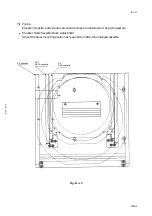
Measure the target window center deviation (x,y) form the hairline.
Fig. B
-
-
-
-
17
③
Turn OFF the ALU switch which is mounted on the right-hand side of the main control
box (located on the right-hand side). Disconnect flat cable connector CN1 and take out the
leftmost PC board (EAUA--1368).
Fig. B
-
-
-
-
18
④
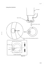
Adjust the PC board mounted DIP switches as indicated below.
Fig. B
-
-
-
-
19
⑤
After completion of adjustment, place the PC board back into its original position,
reconnect the connector, and turn ON the ALU switch.
⑥
Repeat steps
①
through
⑤
until the target wimdow aligns with the hairline.
CRT
Hairline
ALU
Target
Window
P.C.B.
EAUA-1368
●
DSW1 (Vertical Direction)
Each time switch 1 is turned ON, the target window
moves approximately 1 mm down.
●
DSW2 (Horizontal Direction)
Each time switch 1 is turned ON, the target window
moves approximately 1 mm to the right.


