background image

Module Programming

Page 7

Refer to the LED Diagnostics section on pages 11-12 for more information and for troubleshooting purposes.

1

10-pin

D2D

st

1

12-pin

14-pin

nd

2

rd

3

&

Solid

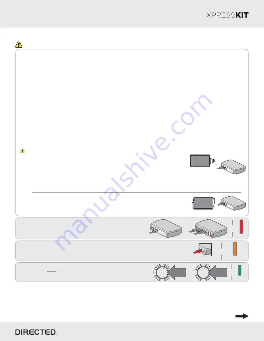
 Connect the 10-pin, 12-pin and 14-pin harnesses to 
DBALL, then wait until the LED turns ON solid red.

2

Enter

 the vehicle, while making sure the factory remote is inside with you.

Press

 5 times on the programming button. The LED turns on solid orange.

&

Press X5

Important

10-pin

D2D

XL202

10-pin

D2D

SmartStart

OR

The DBALL module 

must 

be disconnected from any power source before SmartStart can 

be connected to it. Failing to do so could damage DBALL.

a.

  To ensure that the D2D communication between SmartStart and DBALL works properly, the 

Gray wire must be connected to a ground source (

Rev B 

SmartStart), and the Brown or Blue 

loop must be cut (

Rev A 

SmartStart).

b.

  Do 

NOT 

connect the 2-pin harness (on SmartStart). Power and ground will be provided by 

the DBALL D2D connector.

Connect SmartStart to DBALL using the D2D port.

SmartStart Installation

Connect XL202 to DBALL using the D2D port.

XL202 Installation

Make all the required connections to the vehicle, as described in the wiring diagram(s) found in this guide, and double check to 
ensure everything is correct prior to moving onto the next step.

Note: 

Before connecting either the XL202 or SmartStart module to DBALL, it is important to ensure that the proper feature and 

function programming is selected using XpressVIP (version 4.5 or higher). Visit www.directechs.com to download the latest 
version of the application.

Warning! 

To take advantage of advanced features, you must use XpressVIP 4.5 (and higher) or the Directechs Mobile app.

When the flashing operation is successful, you can proceed with the programming instructions below.

Flashing a module using your computer:

1. Connect the interface module to your computer using the 

XKLoader2.

2. Go to www.directechs.com using Internet Explorer, and 

select the 

Config for RXT

 button.

3. Follow the instructions to select your vehicle, installation 

type, and configure your options.

4. Once you have configured the firmware options, click on the 

FLASH 

button.

Flashing a module using your smartphone or tablet

1. Connect the interface module to your XKLoader3.
2. Launch the Directechs Mobile app on your smartphone or 

tablet.

3. Select 

FLASH YOUR MODULE

 and follow the on screen 

instructions.

Solid Orange

3

Press

 once and 

hold

 the Push-to-Start button to 

turn the ignition ON. The LED flashes green.

Flashes

Green

&

ENGINE

START

STOP

HOLD

&

1X

ENGINE

START

STOP

PUSH

Go to the next page to complete the module programming.

Rev.: 20170407

Platform: DBALL2
Firmware: GM9 Range Extender Ready (RXT) Installation v.2.05+

© 2017 Directed. All rights reserved.

Summary of Contents for XPRESSKIT GM9

Page 1: ...les equipped with a factory installed remote starter This guide is compatible with the GM9 firmware version 2 05 and later Range Extender Ready RXT is used to dramatically increase the factory remote start activation range compared to the factory transmitter Refer to the Quick Reference Guide for more information Buick Cadillac and Chevrolet are registered trademarks and property of their respecti...

Page 2: ...Unlock DL Trunk Hatch Release RS OEM Remote Start Activation using XL 202 or RF kit RS SmartStart ST Brake Status foot brake Buick LaCrosse Smart Key Regal Smart Key Verano Smart Key Cadillac ATS Smart Key CTS Sedan Smart Key Escalade Smart Key SRX Smart Key XTS Smart Key Chevrolet Cruze Smart Key Impala Smart Key Malibu Smart Key Suburban Smart Key Tahoe Smart Key GMC Yukon Smart Key Legend DL OE...

Page 3: ...n on vehicle specific connections Page 3 Wiring Diagram With the exception of the OBDII Diagnostic connector all adapters are displayed from the wire side unless specified otherwise 10 RF Prog Button LED 4 14 12 2 DBALL2 You can connect to either a XL202 RFTD OR a SmartStart module Refer to the SmartStart XL202 Installation Notes for more information Rev 20170407 Platform DBALL2 Firmware GM9 Range...

Page 4: ...ack 4 SW CAN Green 1 Data CAN High Blue 6 Data CAN Low White 14 Data 12V Red 16 Ground Black 4 SW CAN Green 1 Data CAN High Blue 6 Data CAN Low White 14 Data 12V Red White 16 Ground Black 4 SW CAN Dk Green 1 Data CAN High Tan Black 6 Data CAN Low Tan 14 Data 12V Red White 16 Ground Black 4 SW CAN Lt Green 1 Data CAN High Lt Blue 6 Data CAN Low White 14 Data 12V Red Lt Green 16 Ground Black 4 Black...

Page 5: ...d Black 4 SW CAN Green 1 Data CAN High Blue 6 Data CAN Low White 14 Data 12V Red Green 16 Ground Black 4 SW CAN Green 1 Data CAN High Blue 6 Data CAN Low White 14 Data 12V Red Brown 16 Ground Black 4 SW CAN Green 1 Data HS CAN High Blue 6 Data CAN Low White 1 Data 12V Red Violet 16 Ground Black 4 Black 16 OBDII Diagnostic Connector Black 16 Chevrolet Malibu Smart Key 2016 Chevrolet Malibu Smart Ke...

Page 6: ... modules must be connected in a specific order Refer to the Module Programming section for more information 1 Use the D2D Crossover XOVER cable that is provided with XL202 and NOT the one in the DBALL package 2 The modules must be connected in a specific order Refer to the Module Programming section for more information The modules must be connected in a specific order Refer to the Module Programm...

Page 7: ...ing onto the next step Note Before connecting either the XL202 or SmartStart module to DBALL it is important to ensure that the proper feature and function programming is selected using XpressVIP version 4 5 or higher Visit www directechs com to download the latest version of the application Warning To take advantage of advanced features you must use XpressVIP 4 5 and higher or the Directechs Mobi...

Page 8: ...d If required for your installation connect the 10 pin 12 pin harnesses to the module Press and hold the programming button then connect the 14 pin harness to the module 10 pin D2D st 1 12 pin 14 pin nd 2 th 4 rd 3 A module reset will only erase programming performed in the previous steps All settings firmware and settings flashed to the module using the web config tool will not be affected Solid ...

Page 9: ...or arm command w ill be executed at the beginning or end of the sequence it must be controlled by the Remote Starter 2 Safelock Smart OEM Alarm Control w ill behave like a standard Safelock feature on a remote starter It w ill unlock at the beginning of the sequence and relock after start and shutdow n 3 Enabled Smart OEM Alarm Control w ill synchronize w ith the OEM alarm so that it w ill disarm ...

Page 10: ...number of times to indicate the current feature The flashing sequence will repeat until a new command is entered Accessing another feature Press and release the programming button a number of times to advance from the current feature to the next desired feature The LED flashes green slowly the number of times equal to the feature number After a short delay the LED flashes red rapidly to indicate t...

Page 11: ...k the Tan Tan Black wire connections Wake up the data bus by turning the ignition on and try again Bypass data not detected Check the bypass line connection If more than one wire is used make sure they are not inverted Start vehicle using the key to confirm the OEM equipment is still operational External Module Synchronisation OBDII feature not supported Diagnostic data bus not detected Some featu...

Page 12: ...Flashes orange x2 Flashes red x2 Flashes orange x3 Flashes red x3 Flashes orange x4 Flashes red x4 Flashes orange x1 Flashes red x1 RXT Code OEM Remote Start Activation was attempted when RFTD feature is disabled Activated from Web automatically when using RXT flash tool or can be done manually Refer to Feature Programming section for more information RXT start not possible when OEM system is disa...

Page 13: ...F TIME LOSS OF EARNINGS COMMERCIAL LOSS LOSS OF ECONOMIC OPPORTUNITY AND THE LIKE NOTWITHSTANDING THE ABOVE THE MANUFACTURER DOES OFFER A LIMITED WARRANTY TO REPLACE OR REPAIR AT DIRECTED S OPTION THE PARTAS DESCRIBEDABOVE This warranty only covers Parts sold within the United States ofAmerica and Canada Parts sold outside of the United States of America or Canada are sold AS IS and shall have NO ...

Page 14: ...ovide users with easy takeover when entering their Push to Start PTS equipped vehicle once it has been remote started Typically users would have to remote start their vehicle then get inside and press the vehicle start button to perform a takeover There is therefore a physical action required to drive away With Get In and Go technology you simply remote start the vehicle unlock the doors get in an...

Page 15: ... can be modified in some vehicles refer to your vehicle owner s manual for more information A maximum of 2 remote starts can be performed between ignition cycles Runtime Reset The Runtime Reset feature allows the user to return the runtime to its predefined value This can only performed ONCE per remote start RXT Operations Button s Actions Press hold for 1 second to lock Press hold for 1 second to...

Page 16: ...d remote start or security with remote start system Ÿ Lock Arm Ÿ Unlock Disarm Ÿ Remote Car Starter Ÿ Trunk Release Ÿ Panic Ÿ Aux Channels You can also control multiple vehicles great for families and assign more than one user to control a vehicle It s easy with SmartStart But this is only the beginning SmartStart is loaded with additional features including GPS tracking SmartSchedule vehicle stat...

Reviews: