9
D I R E C T H E A L T H C A R E S E R V I C E S . C O . U K
S E R V I C E M A N U A L
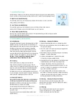
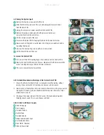
8.9 Taking the System Apart
1
Remove the four lid screws and lift off the lid.
2
Slide the IEC inlet up and out of the case and unplug the 4way connector
from the Rotor PCB.
3
Unplug the compressor power cable from the Control PCB
4
Remove the yellow capillary tube from the pressure transducer
and green hose from the air silencer.
5
Lift the compressor out of the case.
6
To remove the Rotor PCB first unplug the AC and DC power inlet wires.
7
Now disconnect the green air outlet tubes from the grey air outlet connectors
by pulling them apart.
8
Unscrew the x3 mounting screws with a pozi screw driver.
9
Lift the Rotor PCB out of the case.
To remove the Control PCB:
10
First slide off the PCB mounting fingers from either end of the Control PCB.
11
Now tip the Control PCB back into the case. Make sure that the brown switches
are not catching before you lift the PCB clear of the case.
12
The case is now empty of all assemblies.
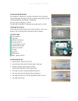
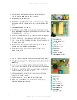
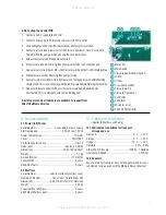
8.9.1 Detailed Breakdown & Workings of the Rotor & Rotor PCB
1. Ensure that the Air Distributor Rotor is slowly and smoothly turning, without
jerking. It does not matter if it is turning clockwise or anti-clockwise.
2. Now disconnect the mattress hose and connect a flow meter to the grey air outlet.
During the 12 minute cycle you should be able to measure a flow of 3-4 litres /
minute from each port.
3. Finally pull the power cord out of the IEC socket. The mains failure Audible
Warning should sound. This is a continuous solid tone.
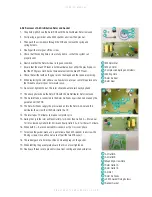
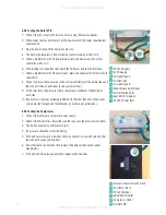
8.9.2 AC Inlet & DC Power Supply
240v AC Supply
5v DC Supply
Air Outlet Tube A
Air Inlet Tube
Air Outlet tube B
Mains Failure Switch Input
Air Distribution Rotor
Sync Motor / Gearbox
240v AC Power Inlet
1
2
3
4
5
6
7
8
9
1
2
3
4
5
6
7
8
9
12
11
10
9
10
8
7
2
5
6
3


