D I R E C T H E A L T H C A R E S E R V I C E S . C O . U K
1 2
D Y N A - F O R M M E R C U R Y A D V A N C E
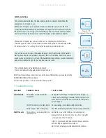
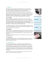
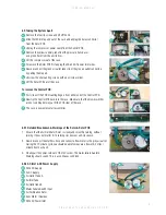
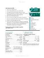
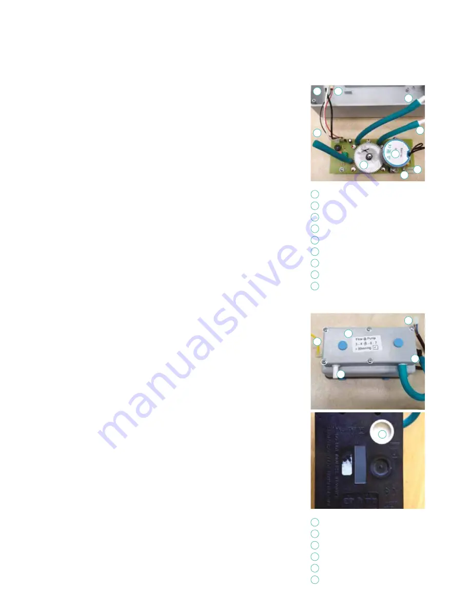
8.9.4 Testing the Rotor PCB
1. Connect the IEC socket to the inlet connector, using the four way header.
2. With a mains cable connected turn on the power switch. The mains failure buzzer
should sound
3. Plug in a power lead and the buzzer should stop.
4. The Rotor will slowly turn, either clockwise or anti-clockwise. Either is OK.
5. Attach a multimeter to the AC power leads ( black and white wires) The meter
should show 240 v AC.
6. If the readings are dead then check both the PCB fuses and the IEC inlet fuse.
7. Attach a multimeter to the DC power leads ( black and red wires) The meter should
show 5vDC.
8. Connect a pressurized air source ( needs at least 80mmHg) to the air Inlet tube and
then connect the Air outlet tubes to two pressure meters.
9. As the rotor turns the pressure meters should read a minimum of 80mmHg on
each side.
10. If one meter is reading considerably different to the other then check the gasket
screws are tight enough and that the tubes do not have any perforations.
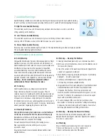
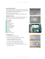
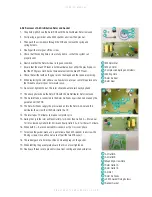
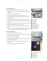
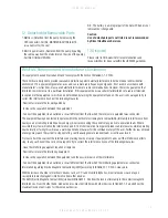
8.9.5 Testing the Compressor
1. Connect the compressor to a mains power supply.
2. Connect the Air outlet to a flow meter and the capil- lary tube to a pressure meter.
3. The Air flow should be a minimum of 4 lpm
4. the pressure should be at least 80mmHg
5 If the air flow or pressure is low then check air silencer is screwed down and that
tubes do not have any perforations.
6. If no other faults can be found then replace the pump valve body and rubber
diaphragms.
7. If the air filter felt is grey and dirty then replace with a new item.
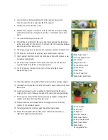
240v AC Supply
5v DC Supply
Air Outlet Tube A
Air Inlet Tube
Air Outlet tube B
Mains Failure Switch Input
Air Distribution Rotor
Sync Motor / Gearbox
240v AC Power Inlet
1
2
3
4
5
6
7
8
9
1
2
3
5
4
6
9
8
7
1
2
3
5
6
4
Pressure transducer connection
Air silencer block
240v 50Hz Input
Smoothed Air outlet
Compressor Outlet
Air Inlet Filter
1
2
3
4
5
6


