1 1
D I R E C T H E A L T H C A R E S E R V I C E S . C O . U K
S E R V I C E M A N U A L
8.9.3 Removal of Air Distribution Rotor and Gasket
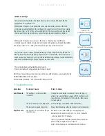
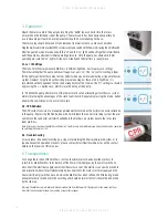
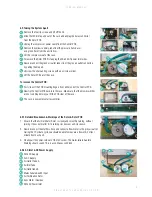
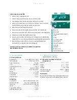
1. The photo (right) shows the Rotor PCB with the Air Distributor Rotor removed.
2. Firstly using a pozi driver and an M4 spanner unscrew the nyloc nut.
3. Then push the screw down through the PCB and remove the spring and
spring holders.
4. Finally pull the rotor gear off the screw.
5. Check that the venting hole is clear of any debris, so that the system can
properly vent.
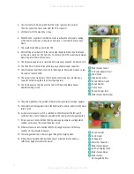
6. Next check that the Rotor Air Seal is in good condition.
7. Ensure that the blue PPT foam is not delaminated from either the plastic gear or
that the PTFE glass cloth has not delaminated from the Blue PPT foam.
8. Check that all the teeth on the gear are not damaged and that none are missing.
9. When replacing the rotor either use a new nyloc nut or put some thread lock onto
the thread to ensure it does not vibrate loose.
10. Do not over tighten the nut. The rotor should be able to turn easily by hand.
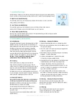
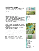
11. The above photo shows the Rotor PCB with the Air Distributor Rotor removed.
12. The Air Inlet tube is connected to the Rotor Air Feeds by air channels made by the
gasket under the PCB.
13. The Rotor Air Feeds supply the pressurized air into the Rotor Air Seal and this
distributes the air to either the Rotor Outlet A or B.
14. The rotor takes 12 minutes to make a complete cycle.
15. During the cycle the rotor will feed Outlet A for 5 mins then Outlets A + B for about
1 min fol- lowed by Outlet B for 5 mins and finally Outlets A + B for the last 1 minute.
16. When both A + B are connected this is known as the ‘crossover’ phase.
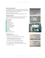
17. To remove the gasket plate, use a pozi driver and an M5 spanner to unscrew the
5 fixing screws. Once all five nuts are off pull the two PCBs apart.
18. The rubber gasket is held in position by mounting lugs on the gasket.
19. When refitting the gasket plate ensure that it is not over tightened.
20. Finally use thread lock to prevent screws from coming undone by vibration.
M4 Nyloc Nut
M4 x 50mm
Compression Spring and Holders
Venting Hole
Rotor Air Seal
Rotor Gear
1
2
3
4
5
6
1
2
3
4
5
6
1
2
3
5
4
6
7
8
Air Outlet A
Air Outlet B
Mounting Screw Hole
Rotor Outlet A
Rotor Outlet B
Air Inlet
Rotor Air Feeds
x5 M5 Gasket Fixing Screws
Rubber Gasket
1
2
3
4
5
6
7
8
9
9


