DINSEO DIX TIG GO 1806.M AC/DC Operation Manual Download Page 16

16


ELECTRODE DIAMETER

For TIG welding with HF ignition, it allows you to use the 
relevant key to set the diameter of the tungsten electrode 
used, and/or to change it using the ENCODER knob, in 
order to achieve the best control of the AC arc in a syn-
ergic manner.

WARNING: The electrode diameter CANNOT be selected when 
the welding power source is set for the SPECIAL configuration.


WELDING MODE

The welding power source offers 

4

 welding modes. Each time 

the button is pushed, the welding power source switches to se-
lect the welding mode indicated by the LED that stays lit, in the 
following order:

 L5 

  2 STROKES

 L6 

  4 STROKES

 L7 

 SWITCH

 L8 

  SPOT WELDING

L5

L6

L7

L8

SWITCH

 L5 

  2 STROKES

When the torch button is pushed welding begins starting with the 
INITIAL CURRENT (if SLOPE UP is selected), while when it is re-
leased welding ends when the FINAL CURRENT is reached (if 
SLOPE DOWN is set).

 L6 

  4 STROKES

TIG welding takes place as follows:

• 

When the torch button is pushed welding begins at the INITIAL 
current.

• 

When the torch button is released the SLOPE UP process is 
carried out (if applicable) and the current returns to the PRIN-
CIPAL value 

 I

.

• 

When the torch button is pushed the SLOPE DOWN process 
is carried out (if applicable) and the current returns to the FI-
NAL value.

• 

When the button is released the welding SWITCH ends.

 L7 

 SWITCH

When this function has been activated, TIG welding takes place 
as follows: 

• 

When the torch button is pushed welding begins at the INITIAL 
current.

• 

When the torch button is released the SLOPE UP process is 
carried out (if applicable) and the current returns to the PRIN-
CIPAL value 

 I

.

• 

When the SWITCH button is pressed and released within less 
than 1 second the welding current goes to the SWITCH value 
(

 I

), and by repeating this operating you can move between the 

two current levels (

 I

), (

 I

) an infinite number of times.

• 

When the torch button is pushed and held down (for longer than 
1 second) you exit the SWITCH, the SLOPE DOWN process is 
carried out (if applicable) and the current returns to the FINAL 
value. When the torch button is released the welding SWITCH 
ends.

This welding mode is especially indicated for welding profiles with 
different thickness, where continuous current variation is required. 
Also, when welding aluminium, it allows you to have a higher initial 
current, thereby facilitating pre-heating of the workpiece. 

 L8 

  SPOT WELDING

This can be used by pushing the torch button to spot weld for a pre-
set period of time (in seconds) at the end of which the arc switches 
off automatically. The tack welding function is divided into 3 types:

• 

TIG AC and TIG LIFT DC tack welding.

• 

TIG HF DC tack welding with a single DIX ARC COOL SPOT 
point.

• 

TIG HF DC tack welding with a Multi-DIX ARC COOL SPOT 
function.

See the relevant paragraphs in the subsequent pages of this man-
ual.


DISPLAY

Displays the selections made using the various Keys (with corre-
sponding LED on or flashing) and regulated using the ENCOD-
ER knob.

The 

 button can also be used to view:

 L32 

 AMPERE (CURRENT )

• 

When the welding power source is in stand-by, the 
Amps (A) set.

• 

When the welding power source is welding the real 
Amps (A) at which the operator is actually welding.

WARNING: LED 

 L32 

 switched on and steady. 

 L33 

 VOLT (VOLTAGE)

• 

The actual VOLTS (V) at the welding clamps (the 
value displayed CANNOT BE CHANGED OR 
REGULATED).

WARNING: LED 

 L33 

 switched on and steady.


ENCODER knob

This is used to regulate and change the welding 
parameters, according to which LED is switched 
on and the value shown on the DISPLAY, which 
is necessary for the welding power source to work 
correctly.


SAVE “MEM”

Used to save the parameters for the welding programs.


PROGRAM “PRG”

Used to call up welding programs.
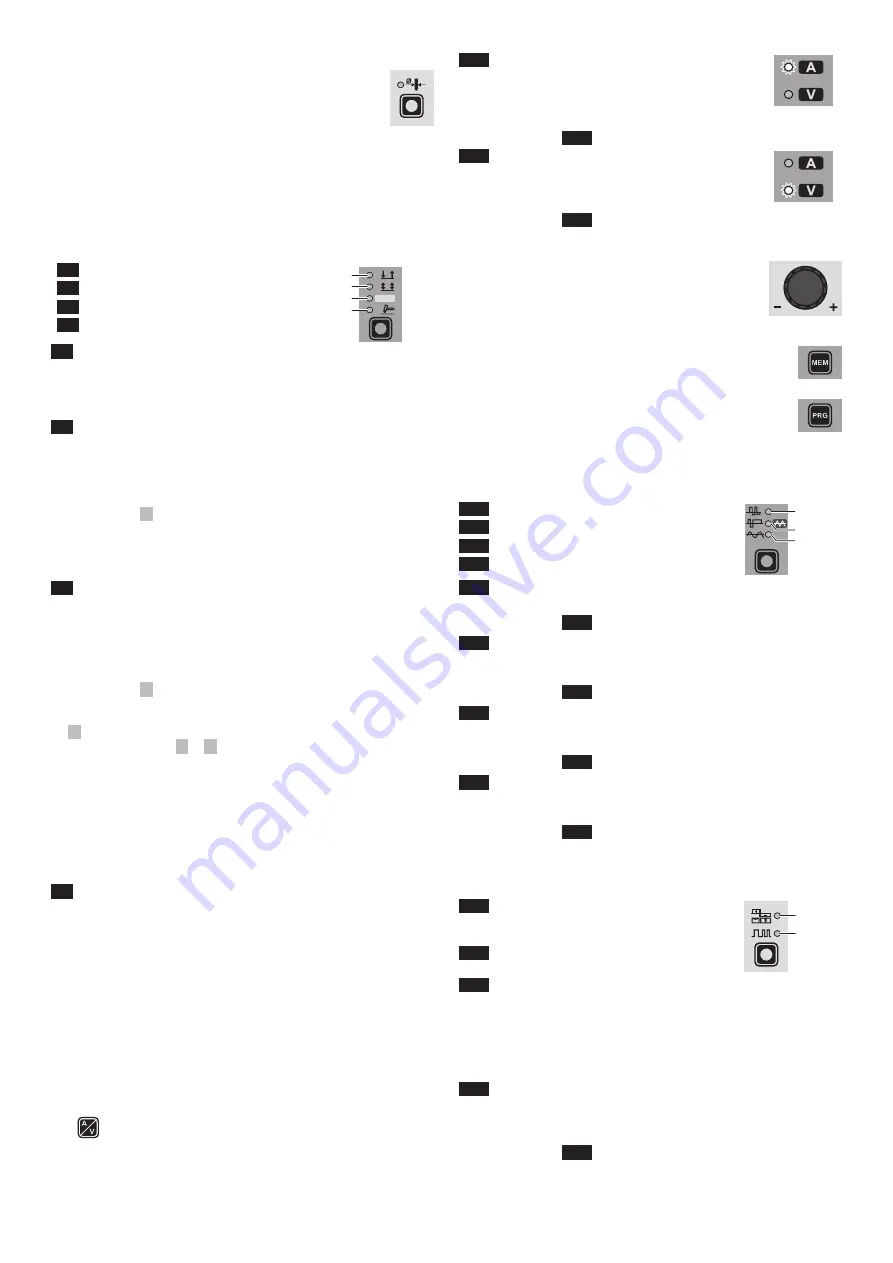
 

WAVE

During TIG AC welding with HF ignition, it makes it possible to con-
trol the following wave shapes:

 L24 

 DYNAMIC TIG

 L25 

 SPEED TIG

 L25 

 COLD TIG

 L26 

 SOFT TIG

WAVE

L24
L25

L26

 L24 

 DYNAMIC TIG

Square wave: highly dynamic arc for all applications.

WARNING: LED 

 L24 

 switched on and steady.

 L25 

 SPEED TIG

Mixed wave: excellent penetration with high welding speed and 
low electrode consumption.

WARNING: LED 

 L25 

 switched on and steady.

 L25 

 COLD TIG

Triangular wave: low heat generation with reduced distortion, ide-
al for minor thicknesses.

WARNING: LED 

 L25 

 switched on and flashing. 

 L26 

 SOFT TIG

Sinusoidal wave: gentle, soft arc with low noise, ideal for aver-
age thicknesses.

WARNING: LED 

 L26 

 switched on and steady.


BALANCING and FREQUENCY

During TIG AC welding with HF ignition, it makes it possible to set 
one of the following parameters, using the relevant key: 

 L30 

 BALANCING of the TIME and 

AMPLITUDE of the AC welding 
current (BALANCE PLUS)

 L31 

 FREQUENCY of the AC welding 

current

L30
L31

 L30 

 BALANCING of the TIME and AMPLITUDE of the AC 

welding current (BALANCE PLUS)

It is possible to adjust both the time (t) and the amplitude of the 
current (I) independently or simultaneously, using positive or neg-
ative values for the time the electrode stays in place. These set-
tings ensure perfect control of penetration and cleanliness, with a 
drastic reduction in side incisions.

 L31 

 FREQUENCY of the AC welding current

The high frequency makes it possible to weld minor thicknesses 
with excellent results, while the low frequency is ideal for welding 
average thicknesses, or where edge preparation is poor. 

WARNING: LED 

 L31 

 switched on and flashing.

Summary of Contents for DIX TIG GO 1806.M AC/DC

Page 1: ...ing Power Source S C H W E I S S E N W E L D I N G W E L D I N G S C H W E I S S E N S C H W E I S S E N Keep in secure area for future reference Operations manual DIX TIG GO 1806 M AC DC DIX TIG GO 2...

Page 2: ...lding machines are Innovative and compact design Compact size and light weight for easy transportation Metallic main structure with shock proof plastic front panel Protective visor on the control pane...

Page 3: ...ent in complete safety for a period of work of X of the total us age time The regulations in force establish the total usage time to be 10 minutes The work cycle is considered to be X of this period o...

Page 4: ...ertures made in the frame The welding unit is characterised by the following levels Protection level IP 23 S indicates that the equipment can be used both indoors and outdoors Use class S means that t...

Page 5: ...le Cutting robot or for automatic equipment Connect the cable to the analogue digital interface as shown in figure Pos 2 Fig B To connect the other end of this cable see the diagram in the man ualfor...

Page 6: ...ut the electrode at the point at which welding is to begin put the TIG torch at an angle so that the edge of the gas nozzle is not on top of the piece to be welded keeping contact be tween the point o...

Page 7: ...ic emission Much attention must be afforded so that the ground connection of the part to be welded does not increase the risk of accident to the user or the risk of dam age to other electric equipment...

Page 8: ...an emp ty programme between saved ones NOTE The value shown on the display during welding represents the effective current output with all types of control The digital control unit of the welding pow...

Page 9: ...th increased risk of electroshock Product suitable for free circulation in the European Community Danger High voltage Grounding Positive pole snap in connector Negative pole snap in connector Connecto...

Page 10: ...10 Wiring diagram DIX TIG GO 1806 M AC DC...

Page 11: ...11 2101WA31...

Page 12: ...12 Wiring diagram DIX TIG GO 2506 M AC DC...

Page 13: ...13 2101WB09...

Page 14: ...tal interface PCB 31 Inverter PCB 32 Automation interface isolation board optional extra 33 Secondary circuit diodes PCB 34 Secondary circuit PCB 35 EMC filter PCB 36 High frequency HF PCB 37 Secondar...

Page 15: ...L4 DIX TIG GO 1806 M I1 SYN FAST SLOW VRD HF AC DC DC HF HOT START ARC FORCE Ib Tb Tp f Ip I2 MEM PRG PULSE PULSE ULTRA FAST WAVE WAVE A V A V SWITCH SWITCH WELDING PARAMETERS ENCODER knob DISPLAY VR...

Page 16: ...on is divided into 3 types TIG AC and TIG LIFT DC tack welding TIG HF DC tack welding with a single DIX ARC COOL SPOT point TIG HF DC tack welding with a Multi DIX ARC COOL SPOT function See the relev...

Page 17: ...rce is activated this allows you to select the follow ing welding parameters based on which LED is flashing L12 PRE GAS duration L13 SLOPE UP duration L14 BASE current duration Tb WARNING This can onl...

Page 18: ...set at the start of the welding process thereby reducing the risk of poor fu sion at the start of the joint L9 HOT START 00 100 MMA ARC FORCE Regulates in percentage terms the dynamic characteristics...

Page 19: ...deal for minor thicknesses WARNING LED L25 switched on and flashing The display shows the RMS current value for pre set ting and welding 1806 M AC DC 2506 M AC DC TIG AC COLD TIG 16 127 A 5 173 A I A...

Page 20: ...essary of the example shown below Display t 15 65 35 I 20 120 80 I A t s 6 FREQUENCY CONTROL IN AC 40 250 Hz This controls the frequency for the various wave shapes for better directional control redu...

Page 21: ...S SELECTION T10 key a number of times it is possible to set the various TIG WELDING PARAMETERS see the TIG AC and DC Weld ing paragraph WELDING PARAMETERS 7 Once the all the selections regulations ind...

Page 22: ...ctually welding T5 Multi spot welding with Multi DIX ARC COOL SPOT function with TIG HF DC welding The Multi DIX ARC COOL SPOT function can be used for cold tacking in quick succession to further exte...

Page 23: ...STROKES or SWITCH welding mode is activated L13 SLOPE UP duration 0 0 5 0 sec L11 PRINCIPAL welding CURRENT I1 1806 M AC DC 2506 M AC DC TIG DC 5 220 A 5 300 A TIG AC DYNAMIC TIG SPEED TIG COLD TIG SO...

Page 24: ...T Ib 1806 M AC DC 2506 M AC DC 5 220 A 5 300 A L21 PEAK CURRENT Ip 1806 M AC DC 2506 M AC DC 5 220 A 5 300 A PULSE SYN FAST SLOW T5 L23 PULSATION FREQUENCY f 1806 M AC DC 2506 M AC DC FAST 0 5 500 Hz...

Page 25: ...pulsation is active SLOW LED on Press the WELDING MODE SELECTION key T9 until the SWITCH welding mode is active SWITCH LED on Press the WELDING PARAMETERS SELEC TION Key T10 a number of times to set t...

Page 26: ...ARAM ETERS defined as being BASIC L11 L19 L22 T10 L11 L21 1st LEVEL PEAK CURRENT I1p 1806 M AC DC 2506 M AC DC 25 220 A 25 300 A WARNING When the SYN PULSE function is active the 1st level PEAK CURREN...

Page 27: ...be programmed when the TIG AC with HF ignition or TIG DC with HF ignition welding processes and the 2 STROKES welding mode are used To exit the setting phase hold the WELDING PARAMETERS SE LECTION ke...

Page 28: ...e set values as they cannot edit any type of parameter function To edit switch to MANUAL welding mode MANUAL WELDING To go back to set edit the parameters selected or to create a new program proceed a...

Page 29: ...nd prevents welding During welding the VRD LED turns RED which does not indicate any malfunction on the welding power source but that the VRD device has been deactivated to allow welding T10 Auxiliary...

Page 30: ...Display Diagnosis E01 PRESSURE SWITCH This message appears when the cooling equipment is connected to the welding power source and its pressure switch does not close due to a lack of pressure in the...

Reviews: