Rev 1.39 03.10.17
Firmware Version 143 ff.
Dingo 4040P Reference Manual
33
float condition (i.e. almost fully charged) before
the EMOD condition will become active.
When the Dingo enters Float state, EMOD will
become active and, as STRT is always true and
TMOD is always true, the pumping will start if
the tank is not full. .
Note: BSET=2, LSET or GSET=4
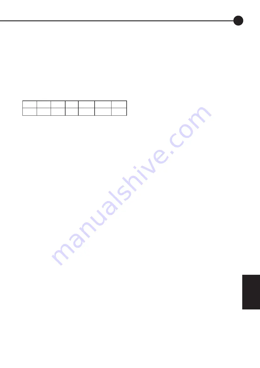
4. Water garden for 5 minutes every 100
min from 2pm until nightfall
STRT RATE STOP RUN EMOD TMOD TIME
14
100 14
5
3
7
14.0
The STRT condition is true every 100 minutes,
i.e. repeated start at 100 minute intervals. The
STOP condition causes the event to run for only
5 minutes after each event start. This cycle will
continue while it is daytime (EMOD = 3) and it is
after 2pm (TMOD = 7, TIME = 14.0).
Note: LSET or GSET = 4 and BSET=0.
8.0 Setting up a Larger System
The Dingo can become a controller for a larger
system. By adding switching stages larger charge
and load currents can be controlled.
Up to 12 external switch devices can
be controlled. These attach to the serial
communication port. This is a balanced 2 wire
(RS485) bus running a communication protocol
compatible with Modbus systems.
As well, up to 4 external current sensors can be
added to allow measurements from other charge
sources or loads to be included in the total
system measurements. This might be a backup
generator or an inverter.
8.1 Reading ‘External’ information
The charge or load currents from devices
plugged into the bus are called ‘external’ or EXT
for short. They appear in the charge, load, IN and
OUT displays after the internal (i.e. actually going
through the Dingo) readings. Because the current
from an external device might be in either the
charge (into the battery) or load (out of the
battery) direction, the external devices appear in
both the charge and load displays. In the case of
an external generator, the charge display would
show the generator current and the load display
would always be zero. In the case of an inverter/
charger, the current could either be in either
direction and either the load or charge will be
non zero depending on direction.
8.2 Controlling external switches
An external switch device must be controlled by
something. The Dingo allows each switch to be
controlled by one of these four internal functions.
1. The battery charge controller
2. Low voltage load disconnect
3. Alarm
4. Event Control
If the external switch is a maximum power point
tracker, then it is only controlled by the charge
controller. The charge controller sends the
MPPT the target voltage and the current battery
voltage. The MPPT then tries to achieve the
desired target voltage.
Selection of control for on/off switches is done
in the SET/MODE/ESET menu (see section
7.5.3). It is necessary to set the control for each
external switch attached. Because it is sometimes
necessary for the switch to work in the opposite
sense to normal, it is possible to select the
inverse of each control. (e.g. for shunt regulation)
The switches are numbered 1 to 9 then A, B and
C.
When a switch is being controlled by the charge
controller it is turned on or off to try to maintain
the controllers target voltage. The controller
tries to reduce the amount of switching to a
minimum to reduce any electrical interference
caused by switching.
8.3 Connecting external devices
Each device connected to the controller must be
discovered by the controller and given a number.
There are two ways to do this. Each device
will have a means to set its own number. Each
device must have its own number and no two
numbers can be the same. When connected, the
device will display information or be controlled
according to that number.
8


