UL_–53
©
Dinel, s.r.o.
18
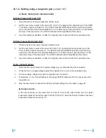
Setting of lower limit 4 mA (0 V)
1. Drain the tank to the lower measured surface level.
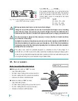
2. Set the level meter output to the value of 4 mA (0 V) by applying the magnetic pen to the EMP-
TY sensitive area for at least 2 s. The STATE indicator LED flashes slowly. Hold the magnetic
pen on the flat area for at least additional 3 s to confirm the set value and store it in the internal
memory of the level meter. The STATE indicator LED briefly flashes three times.
3. Any other setting is possible 2 s after the magnetic pen is removed from the sensitive area.
Setting of upper limit 20 mA (10 V)
1. Fill the tank up to the upper measured surface level.
2. Set the level meter output to the value of 20 mA (10 V) by applying the magnetic pen to the
FULL sensitive area for at least 2 s. The STATE indicator LED flashes slowly. Hold the mag
-
netic pen on the flat area for at least additional 3 s to confirm the set value and store it in the
internal memory of the level meter. The STATE indicator LED briefly flashes three times.
3. Any other setting is possible 2 s after the magnetic pen is removed from the sensitive area.
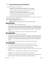
Factory default settings
1. Disconnect the level meter from supply voltage (e.g. by disconnecting the connector).
2. While there is no supply voltage, apply the magnetic pen on one of the sensitive areas.
3. Connect supply voltage and keep the magnetic pen in position.
4.
Wait approx. 4 s for 3 short flashes of the orange STATE indicator LED. You can remove the
magnetic pen.
5. Now the level meter is restored into factory default settings. See the table on page 25.
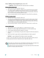
12.1.2.
Setting using
a magnetic pen
(version “M”)
a)
Basic mode
(level measurement)
b)
Inverse mode
In the inverse mode, set the lower limit of 4 mA (0 V) when the tank is filled up to the upper
measured surface level and the upper limit of 20 mA (10 V) when the tank is drained to the lower
measured surface level
see Fig. 32.
Summary of Contents for ULM-53 series
Page 2: ......
Page 27: ...27 Dinel s r o UL_ 53 ...


